


18
Temperature and Pressure
Relief Valve
For protection against excessive pressures and tempera-
tures, a temperature and pressure relief valve must be
installed in the opening marked “T & P RELIEF VALVE”.
This valve must be design certified by a nationally recog-
nized testing laboratory that maintains periodic inspection
of the production of listed equipment or materials as meet-
ing the requirements for Relief Valves and Automatic Shut-
off Devices for Hot Water Supply Systems, ANSI Z21.22.
The function of the temperature and pressure relief valve is
to discharge water in large quantities in the event of exces-
sive temperature or pressure developing in the water heat-
er. The valve’s relief pressure must not exceed the working
pressure of the water heater as stated on the data plate.
Important: Only a new temperature and pressure relief
valve should be used with this water heater. Do not use
an old or existing valve as it may be damaged or not ade-
quate for the working pressure of the new water heater. Do
not place any valve or piping between the relief valve and
the tank.
The Temperature & Pressure Relief Valve:
• Must not be in contact with any electrical part.
• Must be connected to an adequate discharge line.
• Must not be rated higher than the working pressure
shown on the data plate of the water heater.
• The BTUH rating of the T & P valve must be greater
than, or equal to, the input rating of the water heater
The Discharge Line:
• Must not be smaller than the pipe size of the relief
valve or have any reducing coupling installed in the
discharge line.
• Must not be capped, blocked, plugged or contain any
valve between the relief valve and the end of the dis-
charge line.
• Must terminate a maximum of 6 inches above a floor
drain or external to the building.
• Must be capable of withstanding 250°F (121°C) without
distortion.
• Must be installed to allow complete drainage of both
the valve and discharge line.
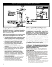
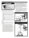
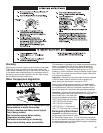
Explosion Hazard
If the temperature and pressure relief valve
is dripping or leaking, have a qualified
service technician replace it.
• Do not plug valve.
• Do not remove valve.
Failure to follow these instructions can
result in death or explosion.
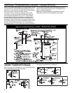
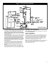
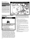
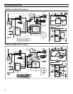
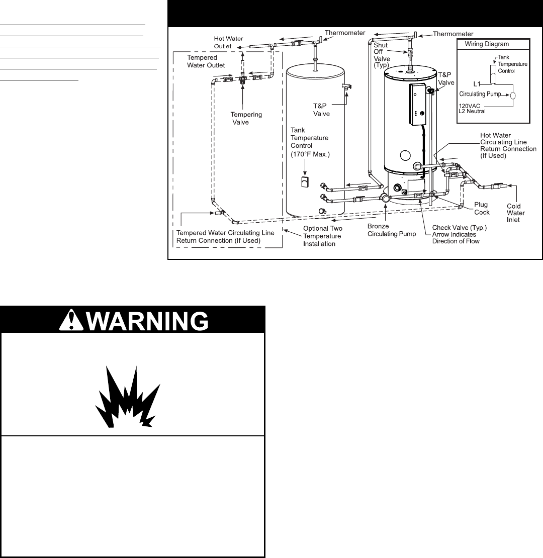
Figure 18: Polaris with Auxillary Storage Tank - One or Two
Temperature System (With or Without Building Recirculation)
Notes on Figure 18:
If tank temperature is set above
120°F and water is supplied for
domestic use (hand washing, show-
ering, etc.) a tempering valve must
be installed in the hot water line to
domestic fixtures.
Installation must conform to local
code requirements. If a check valve
is installed in the cold water sup-
ply line, an expansion tank must be
installed between the check valve
and the water heater’s cold water
inlet. Set storage tank temperature
five degrees lower than the water
heater’s temperature setting. Using
the plug cock in the recirculating
line, adjust the flow in the recirculat-
ing line to five gallons per minute.
*100 Gallon Model Shown.