


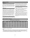
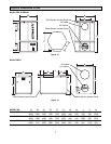
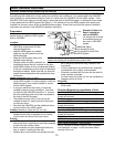
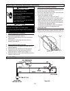
Typical Return to Return Application
For homes with horizontal forced air handler/furnace
systems. (Air handler/furnace is shown in an typical
attic. See figure 7.)
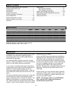
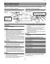
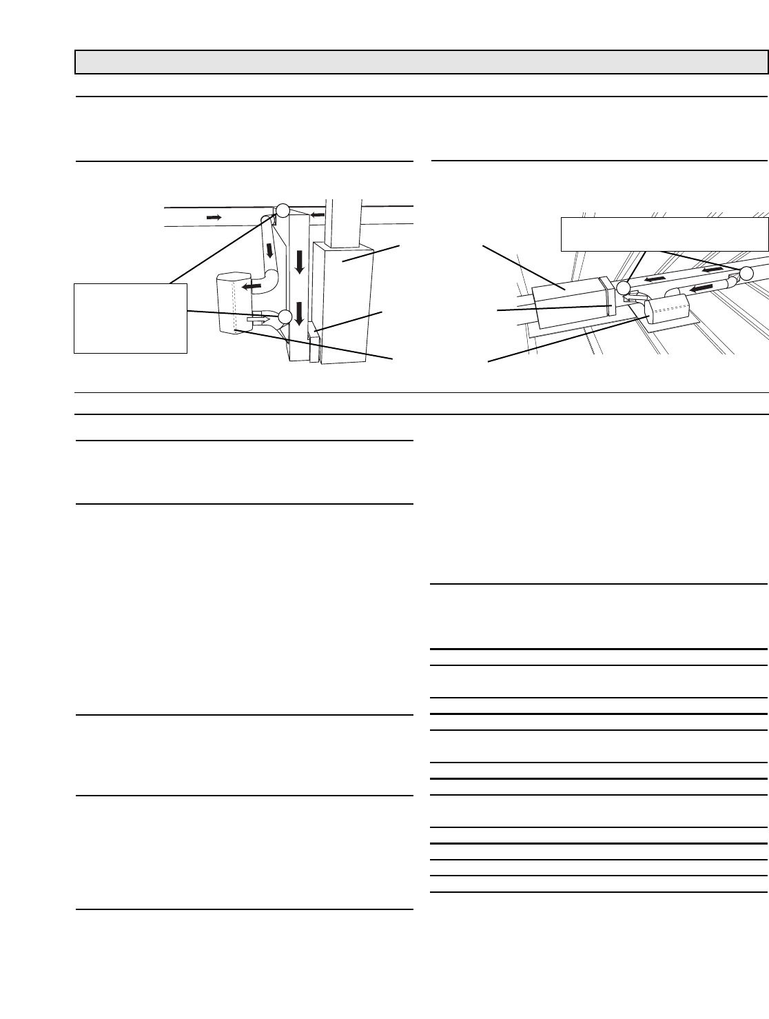
Typical Return to Return Application
For homes with upflow forced air handler/furnace sys-
tems.(Air handler/furnace is shown in a typical base-
ment. See
Figure 6.)
9
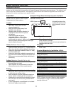
Dealer Installation Instructions
Forced air handler/furnace systems:
The HEPA system should be installed as a bypass system, with part of the return ducted into the HEPA system. The
filtered air is then rerouted back into the return air, and continues through the system to be heated/cooled.
Figure 14.
Figure 15.
Preparation:
Here are some things to consider as you decide where
to install the HEPA system.
Location:
• Make sure there is room to open the HEPA filter
access panel for filter changes/inspections.
• Keep the HEPA system in a location where you
can still access the air handler/furnace filter.
• Keep the HEPA system away from possible water damage.
•Vibration pads will reduce vibration for installations
where the unit is placed on the floor.
• Install HEPA System on floor or suspended platform.
If the unit is suspended, screws must not penetrate
through the cabinet. Make sure that you have the
proper chains/straps/joists and equipment to keep
unit secure.
Intake (Marked as ‘Air In’ on unit):
• Intake ducts should be installed upstream of any
humidifiers and be installed on the main return.
• Intake duct should be installed at least 6 ft. away
from the outflow duct on the main return.
Outflow (Marked as ‘Clean Air Out’ on unit):
• Outflow duct should be installed as close to the air
handler/furnace inlet as possible but not directly
into the return air elbow of the main return.
• If the unit is being installed independently of any
other system, room diffusers are recommended to
help distribute airflow evenly in the occupied space.
Ducting:
• If HEPA system is installed where inlet and outflow
collars face down, metal elbows must be connected
to both inlet and outflow collars.
• Each connection must be sealed with aluminum
tape or mastic, including all take offs.
• Installed duct runs should be as straight as possi-
ble (if the duct runs are too long, reduced CFM
may result).
• If duct is exposed to unconditioned air, externally
insulated flex duct is highly recommended.
• Externally insulated flex duct can also be used for
noise reduction purposes.
• For best indoor air quality, do not use ductboard or
fiberglass inside of ducts.
Electricity:
• The unit must be plugged into a grounded 120V,
60Hz outlet.
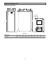
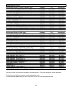
Required Materials for Installation of Unit:
Items for 2500HV & 4000HV
Flex or rigid duct 6” round
(length as required)
Takeoffs Two 6”
Items for 6000V
Flex or rigid duct 10” round & 8” round
(length as required)
Takeoffs One 10” & One 8”
Items for 6500, 8500 & 10000
Flex or rigid duct 10” x 12”
(length as required)
Takeoffs Two 10”x12”
All Models
Aluminum tape or mastic as required
Misc. hanging materials - field provided
NOTE: Be sure to review ‘Rules for Safe Installation
and Operation’ on page 1 of this document before
start-up of this unit.
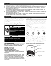
A
A
B
B
Air Handler/
Furnace
Air
Handler/Furnace
Filter
HEPA System
NOTE: This filtration system is an ADDITIONAL filter, and does NOT replace the existing air handler/furnace system filter.
Distance between
A and B should
be 6' to 16' for
best results
Distance between A and B should
be 6' to 16' for best results