


19
accordance with all local codes and the instructions in the follow-
ing sections.
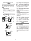
Follow the bullets listed below when installing the drain system.
Refer to the following sections for specific details concerning fur-
nace drain trap installation and drain hose hook ups.
• The drain trap supplied with the furnace must be used.
• The drain line between furnace and drain location must
be constructed of 3/4” PVC or CPVC.
• The drain line between furnace and drain location must
maintain a 1/4 inch per foot downward slope toward
the drain.
• Do not trap the drain line in any other location than at
the drain trap supplied with the furnace.
• Do not route the drain line outside where it may freeze.
• If the drain line is routed through an area which may
see temperatures near or below freezing, precautions
must be taken to prevent condensate from freezing
within the drain line.
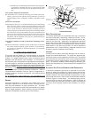
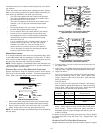
• If an air conditioning coil is installed with the furnace, a
common drain may be used. An open tee must be
installed in the drain line, near the cooling coil, to
relieve positive air pressure from the coil’s plenum.
This is necessary to prohibit any interference with the
function of the furnace’s drain trap.
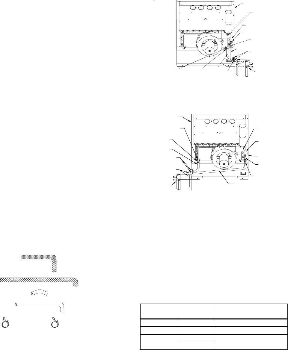
UPRIGHT I NSTALLATIONS
In an upright installation drain hoses are connected to drain ports
on the rubber elbow and the recuperator coil front cover. The drain
lines are then routed through the right or left side panel and into
the drain trap secured to the outside of the cabinet.
NOTE: Refer to Section X, Condensate Drain Lines and Drain Trap
- Alternate Vent/Flue Hose Connections for upright installations
using an alternate vent/flue outlet.
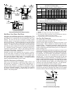
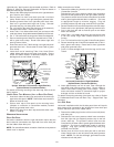
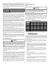
STANDARD RIGHT OR LEFT SIDE DRAIN HOSE CONNECTIONS
Upright installations using the standard vent/flue outlet require
drain hoses to be connected as follows. The following quantity of
hoses, tubes, and hose clamps are provided with the unit.
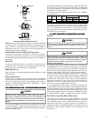
HOSE A
QTY: 1
HOSE B
QTY: 1
TUBE 1
QTY: 1
RED
TUBE 2
QTY: 2
HOSE CLAMPS
QT
Y
:2
GREEN
HOSE CLAMPS
QT
Y
: 3
Hose and Tube Identification
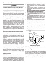
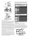
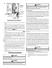
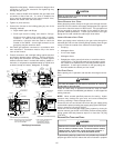
1. Remove the rubber plug from the front cover drain port (right
or left side, depending on the intended drain trap mounting).
2. Secure Hose A to front cover drain port with a red hose
clamp. Route hose to rear side panel grommet hole.
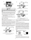
NOTE: For left side drainage, grommets will have to be relocated to
left side panel.
DRAIN
TRAP
FRONT COVER
DRAIN PORT
TUBE(S) 2
GREEN
HOSE
CLAMPS
(
3 PLACES
)
RIGHT SIDE
PANEL
RUBBER ELBOW
DRAIN PORT
TUBE 1
SIDE PANEL
GROMMET
HOLES
HOSE
B
HOSE
A
RUBBER
ELBOW
RED HOSE
CLAMP
RED HOSE CLAMP
Upright “Standard” Connections - Right Side
(Upflow Shown, Counterflow Similar)
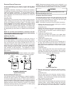
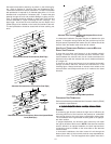
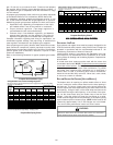
LEFT
SIDE PANEL
FRONT COVER
DRAIN PORT
HOSE A
SIDE PANEL
DRAIN
HOLES
TUBE(S) 2
DRAIN
TRAP
GREEN HOSE
CLAMPS
(3 PLACES)
TUBE 1
RUBBER
ELBOW
HOSE B
RUBBER
ELBOW
DRAIN PORT
RED HOSE
CLAMP
RED HOSE
CLAMP
Upright “Standard” Connections - Left Side
(Upflow Shown, Counterflow Similar)
3. Cut and remove 1/4 inch from the end of the drain port on
the rubber elbow.
4. Insert Tube 1 into rubber elbow drain port and secure with
red hose clamp. Angle tube outward toward front of furnace.
5. Right side drains
Cut 17 3/4 inches from the long end of Hose B and discard.
Secure the remaining hose to Tube 1 with a green hose
clamp. Route the other end of Hose B to front right side
panel grommet hole.
Left side drains
Cut “X” inches from the long end of Hose B and discard.
Refer to table for appropriate length to cut. Secure remaining
hose to Tube 1 with a green hose clamp. Route other end
of Hose B to front left side panel grommet hole.
Cabinet Width
(inches)
Models
(kBTU_Tons)
"X" Length to Cut From Long
End of Hose B
17 1/2 45__30 7 inches
21 70__40 3 1/2 inches
090__50
115__50
24 1/2 None
6. Insert short end of each Tube 2 through side panel grommet
holes. Secure tubes to Hose A and Hose B with green
hose clamps. Ensure hoses and tubes maintain a
downward slope for proper drainage and that they are not
kinked or binding.
For details concerning mounting of the drain trap, refer to Section
X, Condensate Drain Lines and Drain Trap - Upright Drain Trap
Mounting.
ALTERNATE VENT/FLUE DRAIN HOSE CONNECTIONS
Upright installations using the alternate vent/flue outlet will require