


18
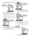
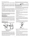
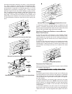
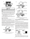
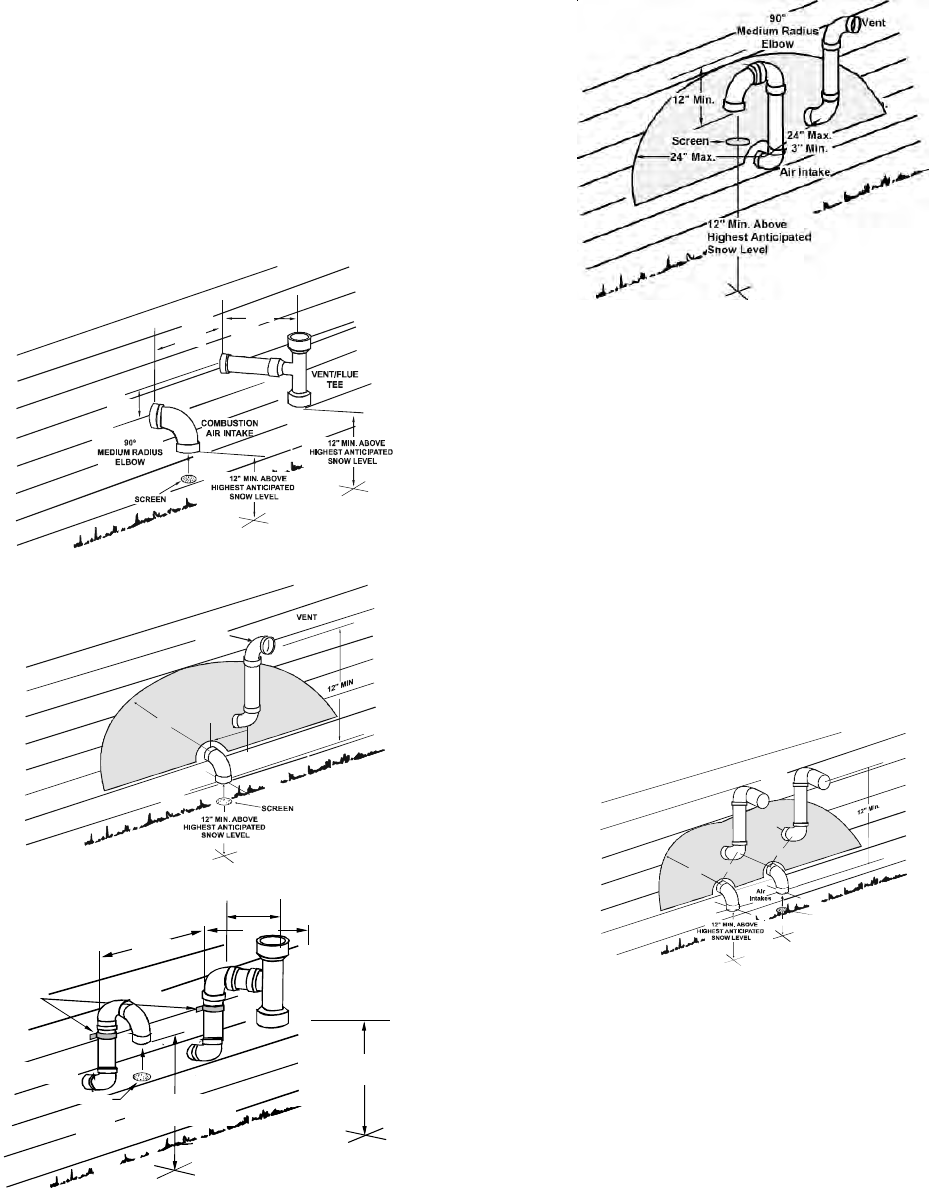
Horizontal terminations should be as shown in the following fig-
ure. Refer to Section IX, Vent/Flue Pipe and Combustion Pipe -
Termination Location for location restrictions. A 2 3/8 inch diameter
wall penetration is required for 2” diameter pipe while a 3 1/2 inch
diameter hole is required for 3” diameter pipe. To secure the pipe
passing through the wall and prohibit damage to piping connec-
tions, a coupling should be installed on either side of the wall and
solvent cemented to a pipe connecting the two couplings. The
pipe length should be the wall thickness plus the depth of the
socket fittings to be installed on the inside and outside of the wall.
The wall penetration should be sealed with silicone caulking ma-
terial.
12" MIN
3" MIN
24" MAX
3" MIN
24" MAX
Standard Horizontal Terminations (Dual Pipe)
24" MAX
3" MIN
24" MAX
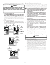
AIR
INTAKE
90°
MEDIUM
RADIUS
ELBOW
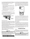
Alternate Horizontal Vent Termination (Dual Pipe)
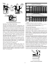
SUPPORT
STRAPS
90°
MEDIUM
RADIUS
ELBOWS
12" MIN.
VENT/FLUE
TEE
SCREEN
COMBUSTION
AIR INTAKE.
12" MIN. ABOVE
HIGHEST ANTICIPATED
SNOW LEVEL
12" MIN. ABOVE
HIGHEST ANTICIPATED
SNOW LEVEL
3" MIN.
24" MAX.
12" MIN
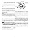
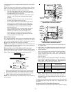
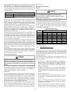
Standard Horizontal Terminations Above Anticipated Snow
Level (Dual Pipe)
Alternate Vent Termination Above Anticipated Snow Level
(Dual Pipe)
In a basement installation, the pipes may be run between the joist
spaces. If the pipes must go below the joist and then up into the
last joist space to penetrate the header, two 45° elbows should be
used to reach the header rather than two 90° elbows.
VENT/INTAKE T ERMINATIONS F OR I NSTALLATION OF MULTIPLE
DIRECT V ENT F URNACES
If more than one direct vent furnace is to be installed vertically
through a common roof top, maintain the same minimum clear-
ances between the exhaust vent and air intake terminations of
adjacent units as with the exhaust vent and air intake terminations
of a single unit.
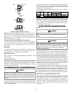
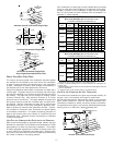
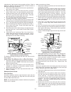
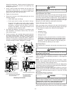
If more than one direct vent furnace is to be installed horizontally
through a common side wall, maintain the clearances as in the
following figure. Always terminate all exhaust vent outlets at the
same elevation and always terminate all air intakes at the same
elevation.
V
ents
24" Max.
3" Min.
12" Min.
Screen
24" Max.
90°
Medium
Radius
Elbows
24" Max.
3" Min.
3" Min.
Horizontal Venting Of Multiple Units
CONCENTRIC V ENT T ERMINATION
Refer to the directions provided with the Concentric Vent Kit (DCVK)
for installation specifications.
X. COX. CO
X. COX. CO
X. CO
NDND
NDND
ND
ENSAENSA
ENSAENSA
ENSA
TE DRAIN LINES & DRAIN TRAPTE DRAIN LINES & DRAIN TRAP
TE DRAIN LINES & DRAIN TRAPTE DRAIN LINES & DRAIN TRAP
TE DRAIN LINES & DRAIN TRAP
GENERAL
A condensing gas furnace achieves its high level of efficiency by
extracting almost all of the heat from the products of combustion
and cooling them to the point where condensation takes place.
The condensate which is generated must be piped to an appropri-
ate drain location.
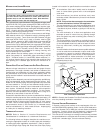
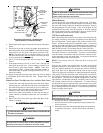
In upright installations, the furnace’s drain hoses may exit either
the right or left side of the furnace. NOTE: If the alternate vent/flue
outlet is utilized in an upright installation, the drain trap and drain
connections must be located on the same side as the alternate
vent/flue outlet.
In horizontal installations, the drain hoses will exit through the
bottom (down side) of the unit with the drain trap suspended be-
neath the furnace. The field-supplied drain system must be in