Manual 2100-518B
Page 24 of 30
1. Check to make sure the loop and unit isolation valves
are completely open and the ush ports are closed and
sealed (see Figure 9D).
2. Geothermal units have two low pressure switches
installed. One switch is intended for Ground Water
Applications (default factory wired - blue wires), and
the second is intended for Ground Loop Applications
(yellow wires). Remove the “blue” wires from the
LPS terminals of the compressor control module
internal of the control panel of the geothermal heat
pump and replace with the yellow low pressure switch
wires (see unit wiring diagram).
3. Check and record the earth loop pressure (use P/T
ports at geothermal heat pump).
Loop Pressure_____IN_____OUT
4. Check and record ow rate.
FLOW RATE - _____GPM
5. Check performance of unit. (Refer to Geothermal
Heat Pump Installation Manual.)
PROCEDURE FOR PRESSURIZING THE
SYSTEM
1. Once system is completely ushed and antifreeze is
added, it can then be pressurized. Perform this by
deadheading the pump by closing the return hose ball
valve. This will increase the pressure on the loop via
the ush cart pump. As the pressure will uctuate
with the seasons (set higher in winter and lower in
summer), it is suggested that the initial loop pressure
be 50-75 psig in winter and 40-50 psig in summer. If
you cannot reach these pressures with the ush cart
pump alone, turn on the fresh water feed to the cart
while still deadheading the pump. The potable water
pressure, along with the pump, will increase the
amount of pressure in the loop.
2. Bleed any air from the inside of the pump. This can
be done by removing the bleed screw from the center
of the pump motor head, allowing a small amount of
uid to drip out. Replace the bleed screw.
3. Rotate the ow center valves to isolate the ush cart
from the rest of the system (see Figure 9D).
4. Turn off the ush cart pump, relieve the pressure on
the hoses and remove them.
5. Replace ow center access plugs and caps.
NOTE: If the ow center is mounted in the horizontal
position, the supply hose must be connected to the lower
ushing port to allow air to pass out of the upper port
during the nal ushing.
PRESSURE/TEMPERATURE PLUGS
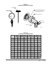
The pressure/temperature plugs (P/T plugs) supplied with
the ground water connectors are provided as a means of
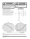
measuring ow and temperature (see Figure 10). The
waterow through the unit can be checked by measuring
the incoming water pressure at the supply pressure P/T and
subtracting the leaving water pressure at the return water
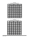
P/T plug. Comparing the differential to the pressure drop/
ow chart (Table 3) will determine the ow rate through
the heat pump.
Example: Model GV51S1 with a measured pressure
drop of 5.1 psig is equivalent to 9 GPM ow.
GPM rates higher than the required minimum ow rates will
not be detrimental to performance. However, insufcient
ow can signicantly reduce capacity, efciency and create
nuisance trips of safety controls, and possibly damage to
components in extreme conditions.
NOTE: Pressure/Temperature probes should be lubricated
with a water-based lubricant prior to gently pushing the
probes into the P/T ports to prevent internal damage.
Thermometers, probes and gauges are available for
conducting these tests.
FLOW CENTER INITIAL STARTUP


