


A-12 - FORM NO. 56041580 - Captor
™
4300, 4800, 5400 / CR 1100, 1200, 1400
A-12 / ENGLISH
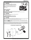
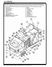
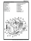
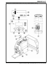
FIGURE 1
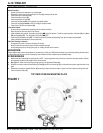
PRE-OPERATIONAL CHECKLIST
Before Each Use:
* Inspect the machine for damage, oil or coolant leaks.
* Squeeze the rubber dust cup on the Engine Air Filter (8) to release built-up dust.
* Check the engine coolant level (23).
* Check the engine oil level (45).
* Check the hydraulic oil level (36).
* Check the Fuel Gauge (DD) on the gasoline, and diesel models.
* Check the Fuel Gauge located on the LP tank (5) for propane model.
* Check the Air Filter Service Indicator (46).
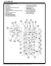
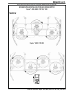
In the Driver’s Seat:
* Be sure that you understand the operating controls and their functions.
* Adjust the seat to allow easy reach of all controls.
* Insert the Master Key and turn the Ignition Key Switch (MM) to the ON position. Check for proper operation of the Horn (B), Hour Meter
(PP) and Headlights (D). Turn the Ignition Key Switch (MM) OFF.
* Check the Parking Brake Latch (GG). The latch must hold its (locked parked) setting rmly with out easily being released.
(Report all defects immediately to service personnel).
Plan Your Cleaning in Advance:
* Arrange long runs with a minimum of stopping or starting.
* Allow 6 inches of broom path overlap to ensure complete coverage.
* Avoid making sharp turns, bumping into posts, or scraping the side of the machine.
MAIN BROOM
Several different main brooms are available for this machine. Contact your Nil sk-Advance dealer if you need help selecting the best broom
for the surface and litter that you will be sweeping. Note: Reference broom maintenance for installation steps.
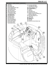
SCRUB BRUSHES
1 Remove side skirt assemblies for easier access. NOTE: Loosen large black knob at the front of each skirt mounting bracket, slide the
skirt assembly forward and lift straight UP and off scrub deck.
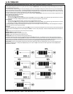
2 See Figure 1. Make sure that the Lug Locking Latch is in the Unlatched Position (A).
3 Slide the scrub brush under the Brush Mounting Plate (B) and lift it so that the lugs (C) on the brush block pass through the holes in the
plate.
4 Rotate the brush into the Installed Position (D) according to rotation directions shown in gure 2 and then rotate the locking latch back
into the Latched Position (E).
TOP VIEW OF BRUSH MOUNTING PLATE