


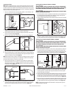
2. Branch lines join the remaining inlets to the trunk line and can be run through
walls, closets, cold air return duct, etc. As with the trunk line, branch lines
should be kept at straight as possible.
3. Avoid gravity drops in the branch line. A branch line located directly below
an overhead trunk line will accumulate dirt due to the effects of gravity. The
result will be a pile of debris at the base of the inlet valve each time it is
opened (Figure 3).
CAUTION: MAKE SURE TUBING WILL NOT OBSTRUCT OR INTERFERE
WITH ELECTRICAL, PLUMBING, OR OTHER MECHANICAL INSTALLATIONS.
Installation into New Construction
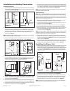
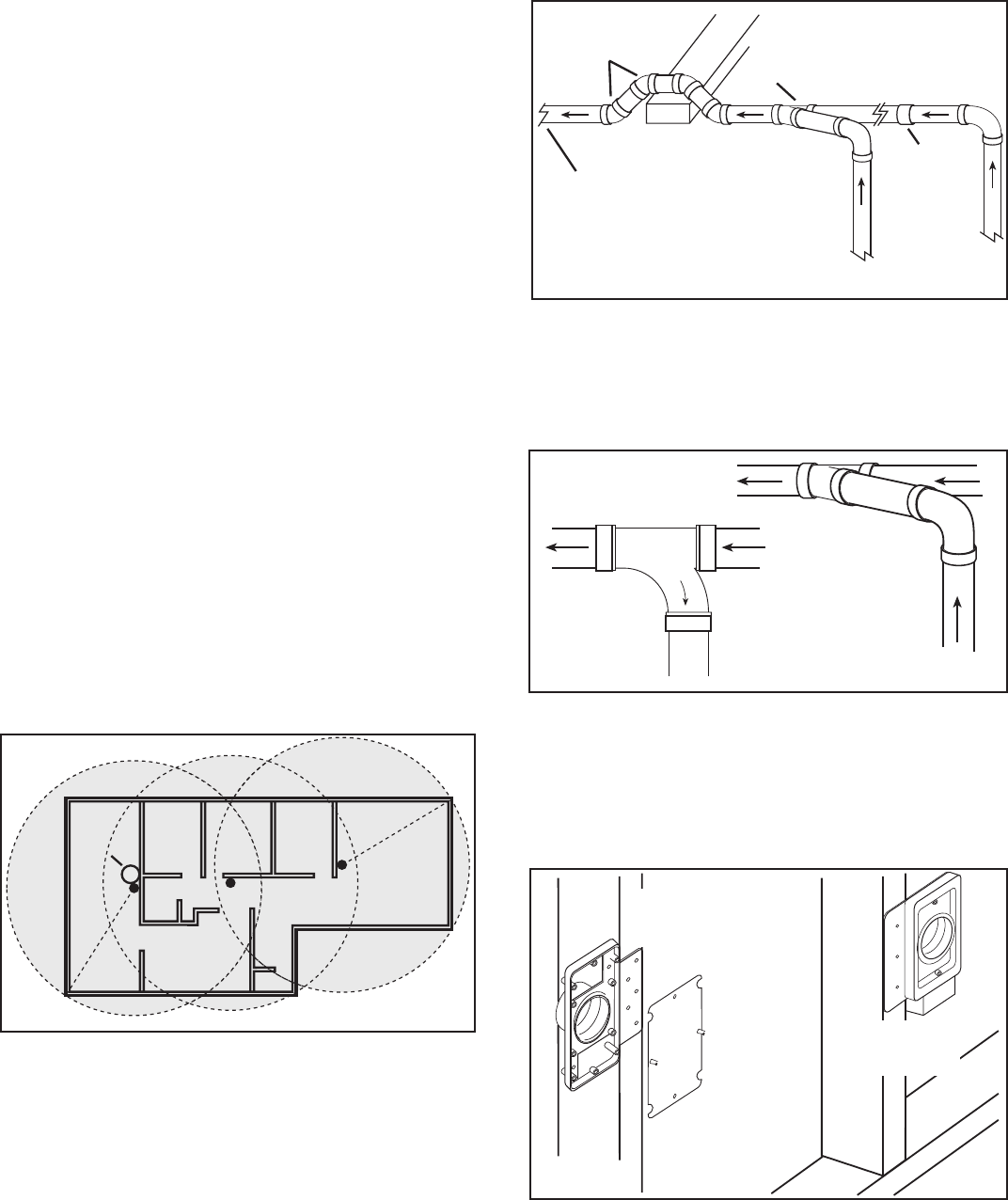
Installing the Inlet Valves
1. Using flush mounting screws (not provided) install the appropriate inlet
mounting plate to the wall stud (Figure 4).
NOTE: Installation height will depend on personal preference, but generally the
inlet is installed 18" above the finished floor.
2. To protect the system during the drywall phase of construction, an optional
CVIV80 plaster guard can be utilized and should be installed at this point.
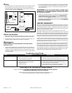
Obstruction
Trunk Line
Branch
Line
45° Elbows
45° Wye
Stop
Coupling
Trunk Line to
Power Unit
Trunk Line to
last Inlet
Wrong
Correct
Debris
Model CVIV70
Standard Inlet
Mounting Plate
Model CVIV80
Plaster Guard
Model CVIV65
Electric Inlet
Mounting Plate
INSTALLATION INSTRUCTIONS
1. Unpack central vacuum power unit from the carton and confirm that all
pieces are present. In addition to the power unit you should have:
1 - Power unit mounting bracket
1 - Inlet valve
1 - Instruction/Safety Sheet
Planning the Installation
The Air King Central Vacuum System consists of three major components. The
power unit, fittings including the inlet valves and tubing, and the tool kit. The
power unit is designed to be permanently mounted in one location with
connections made to the living area with a network of inlets and tubing.
Locating the Power Unit
1. The power unit can be located in a garage, basement, utility room, or any
other room that allows for sufficient ventilation, is dry, and provides
accessibility to the unit for emptying the collection canister.
CAUTION: IF THE POWER UNIT IS INSTALLED IN A CLOSET OR
UTILITY ROOM, IT MUST BE VENTED TO PROVIDE ENOUGH AIR FLOW.
LOUVERED DOORS CAN BE USED. DO NOT MOUNT IN A HIGH AMBIENT
TEMPERATURE AREA SUCH AS ATTIC, FURNACE ROOM, ETC.
NOTE: If venting the unit to the outdoors, avoid venting to areas such as patios
or entranceways.
2. The power unit should be mounted within 5 feet of an acceptable outlet.
Check the electrical specifications of your specific unit to ensure the circuit
is not being overloaded. A dedicated 15 amp circuit should be used.
Locating the Inlet Valves
1. The number of inlet valves will be determined by the layout of your home.
The hose must be able to reach every corner of the home including inside
closets and around furniture. Inlets should be placed in central locations
and avoid placing behind furniture or doors.
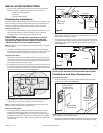
2. Using a 30 foot piece of string or the hose itself, have one person hold one
end to the planned inlet location and have the second person walk around
the room(s) to determine if more inlets are needed. Continue this exercise
until you can reach every area of the home (Figure 1).
3. If the installation is for new constructions and you are working with 1/4"
scale blueprints, use a seven inch string to represent the hose.
NOTE: If an electrical tool kit with a corded hose will be used, make sure an
electrical outlet is located within 5 feet of the inlet.
Planning the Tubing System
1. The tubing system will include a main trunk line that will flow from the
furthest wall inlet back to the power unit and can be run through the
basement or the attic (Figure 2). The trunk line should be kept as straight
as possible to maximize the unit performance. When elbows are needed
45° fittings should be used or if a 90° connection is required, a sweep elbow
should be used.
Figure 1
Living
Room
Bedrm
Garage
Kitchen
Hall
Power
Unit
Bath
Bedrm Bedrm
000000 Rev A. 3-05
www.airkinglimited.com
2 of 16
Figure 2
Figure 3
Figure 4