


,167$//$7,2186,1*$',$0(7(50(7$/)/8(%2;
IMPORTANT: Restrictor plates must be removed. See Fig 15.
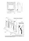
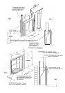
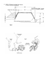
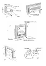
When the metal flue box is to be built-in as a false chimney-breast using timber stud work with a plasterboard facing,
the metal flue box should be enveloped with insulation material such as Rockwool or similar to prevent a build-up of
heat within the structure. Either an air gap of 75mm should be maintained between any combustible materials and
any part of the metal flue box or a minimum of 25mm of insulation material between the metal flue box and the
combustible material. It is important that both the back panel and the appliance are sealed to the metal flue box to
prevent any leakage of flue products or reduction in the flue draught. See Figs 4 & 5.
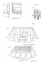
35(&$67)/8(,167$//$7,216
IMPORTANT: Restrictor Plates must be removed. See Fig 15.
See Figs 6 – 8.
&+(&.,1*&21',7,21$1'&203$7,%,/,7<2)7+(&+,01(<
Check that the chimney conforms to the required specifications as previously stated. Examine the condition and
carry out any remedial work as necessary, if the flue has been used for solid fuel it should be swept and a smoke test
carried out to check that satisfactory smoke clearance has been established. If all the smoke is not drawn into the flue,
pre-heat the flue with a blowtorch or similar and re-check. If there is any uncertainty examine for the cause and if
necessary seek expert advice.
*$66833/<
BEFORE COMMENCING WORK, TURN OFF ANY APPLIANCES THAT ARE FED BY THE METER
AND ISOLATE THE GAS SUPPLY BY TURNING OFF AT THE METER
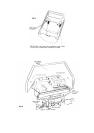
The gas connection to this appliance is made with 8mm o/d rigid or semi rigid tube to a pressure test elbow situated
on the L/H side of the burner as shown below. It is advisable to provide a means of isolating the gas supply to the
appliance for servicing with either a restrictor elbow or isolation cock such as shown below. Provision is made in the
rear L Hand corner of the outer casing to allow a gas supply to be fed to the burner assembly. A blanking plate and
gasket is supplied with cutouts and slots that will enable a seal to be made around the supply pipe. If a restrictor
elbow is to be used, it will be necessary to cut and form the bundy pipe supplied. Any pipe used under the burner
must be in rigid tube such as Bundy, 3 pieces of Bundy are included in the fitting kit to assist the installer. (a) A short
piece for use with a restrictor elbow. (b) A formed section for connection to an isolation cock, and (c) a formed
section for R Hand supply using the inline connector supplied. The inlet pipe support bracket can be removed if
necessary to gain greater access, by unscrewing the Control mounting lock nut and lifting over the spindle, as shown
in Fig 9.
Where a concealed gas supply is used, the installer is reminded of the requirements of BS 6891 1988 dealing with
enclosed pipes. The Standard requires that when a gas pipe is fed through a wall, the pipe should be enclosed in a
tight sleeve to protect against failure caused by movement and shall be constructed to prevent passage of gas either
between the pipe and sleeve or sleeve and wall.
Permanent sealant e.g. fire cement etc. should not be used as these would prevent removal of the firebox if so
required.
Page 6