


2-3
Step 5
Attach DRAIN LINE to DRAIN LINE FITTING. To prevent back pressure from reducing fl ow rate below minimum required for backwash, DRAIN LINE MUST be sized
according to run length and relative height. Be careful not to bend fl exible drain tubing sharply enough to cause "kinking" (if kinking occurs DRAIN LINE MUST
BE REPLACED). Typical examples of proper DRAIN LINE diameters are:
1) 1/2 in. ID up to 15 ft. when discharge is lower than INLET.
2) 5/8 in. ID up to 15 ft. when discharge is slightly higher than INLET.
3) 3/4 in. ID when drain is 25 ft. away and/or drain is installed overhead.
Some areas prohibit the use of fl exible drain lines. Check with local code offi cials prior to installation.
Step 6
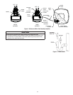
Position DRAIN LINE over drain and secure fi rmly. To prevent backsiphoning of sewer water, provide an air-gap of at least 2 in. or 2 pipe diameters between end
of drain hose and drain (Figure 5). DO NOT raise DRAIN LINE more than 10 ft. above fl oor.
Step 7
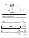
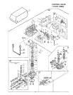
Connect one end of the 3/8 in. poly brine line to BRINE VALVE located on right side of CONTROL VALVE. Connect other end to ELBOW inside of BRINE WELL. Brass
sleeves and plastic ferrules must be used where necessary. (See Figure 3 and CONTROL VALVE PARTS drawing, Section 6).
Step 8
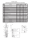
Install OVERFLOW LINE to brine tank OVERFLOW FITTING (Figure 4). Discharge of line must be lower than OVERFLOW FITTING. DO NOT INTERCONNECT OVER-
FLOW LINE WITH VALVE DRAIN LINE (STEP 6).
Step 9
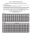
On time clock initiated models, set REGENERATION FREQUENCY. Refer to REGENERATION FREQUENCY SCHEDULES (Section 3) to determine correct frequency,
then refer to HOW TO SET TIME CLOCK REGENERATION CONTROL (Section 3) for instructions on setting frequency. For meter initiated models, refer to HOW TO
SET METER REGENERATION CONTROL.
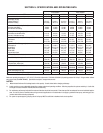
NOTE: Regeneration settings for both time clock and meter initiated models are factory preset for the most effi cient salt use and minimum water consumption
used for regeneration (as little as 50 gallons/89 liters), and conform to the INDUSTRY SALT EFFICIENCY STANDARDS (required by some states). REGENERATION
FREQUENCY SCHEDULES are designed for use with factory regeneration settings (listed in SPECIFICATIONS AND OPERATING DATA, Section 5).
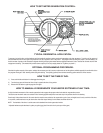
The control valve design permits adjustment of the salt dosage. This adjustment may be necessary when unusual operating conditions exist, such as high con-
centrations of iron or hardness and/or high fl ow rates or daily water consumption. This adjustment is easily performed by loosening the screw holding the white
cam (on backside of timer) and adjusting the pointer to the desired pounds of salt.
NOTE: For salt dosages greater than 15 lbs., grid leg extensions must be attached to bottom of grid legs.
Step 10
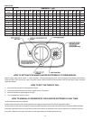
Set TIME OF DAY (refer to appropriate HOW TO SET TIME CLOCK/METER REGENERATION CONTROL, Section 3). When shifting to daylight saving time (and back),
you may wish to adjust TIME OF DAY accordingly.
NOTE: TIME OF REGENERATION is preset for 2:00 a.m. because at this time water consumption is generally minimal (a built-in hard
water bypass does, however, permit water to be drawn during regeneration). Should your lifestyle require regular use of water during
the 2:00 to 3:00 a.m. regeneration period, or if other water treatment equipment is also set for 2:00 a.m. regeneration, the TIME OF
REGENERATION will need changing. To change, adjust time of day on 24-HOUR GEAR ahead or behind actual time of day. For ex-
ample, if 1:00 a.m. regeneration is desired and actual time of day is 10:00 a.m., advance 24-HOUR GEAR one hour to 11:00 a.m.; or,
should 3:00 a.m. regeneration be desired, set gear back one hour to 9:00 a.m.
Step 11
Before loading salt, using a pail or garden hose, add approximately 3 gals. water to brine tank (6 gals. for units with extended grid legs). Then add initial salt fi ll
to brine tank, and one cup full of laundry bleach.
Step 12
Put softener through a complete regeneration - to sanitize the system before use (refer to HOW TO SET TIME CLOCK (or METER) REGENERATION CONTROL for
instructions on manual regeneration.)
Installation is now complete, and your water softener is now ready for service!