


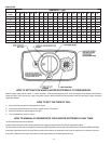

Step 1
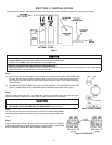
(a) Remove control valve by removing quick connect clamp and using a garden hose or bucket, to fi ll SOFTENER TANK
with water (this fi lling method prevents air entrapment that can cause loss of resin during initial regeneration proce-
dure). Replace control valve. Make sure clamp is reassembled as shown in Figure 2 "LATCH" arrows should point
toward each other.
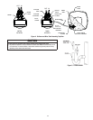
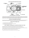
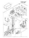
(b) Attach BYPASS VALVE/YOKE ASSEMBLY (Figure 3) using ADAPTER COUPLINGS, CLIPS and SCREWS to CONTROL VALVE
(Figure 4). On Meter initiated models, attach METER between BYPASS VALVE and CONTROL VALVE (Figure 4).
Step 2
Shut off all water at main supply valve. On a PRIVATE WELL SYSTEM, turn off power to pump and drain pressure tank.
Make certain pressure is relieved from complete system by opening nearest faucet to drain system.
CAUTION
To reduce the risk associated with property damage due to water leakage:
• SHUT OFF FUEL OR ELECTRIC POWER SUPPLY TO WATER HEATER after water is shut off.
Step 3
Cut main supply line as required to fi t plumbing INLET and OUTLET of BYPASS VALVE ASSEMBLY.
Use fl exible tubing connections to connect the valve to household plumbing (as shown in sche-
matic).
Step 4
Solder or solvent weld plumbing. DO NOT apply heat to any fi tting connected to BYPASS or
CONTROL VALVE as damage may result to internal parts or connecting adapters. MAKE CERTAIN
WATER FLOW ENTERS THROUGH INLET AND DISCHARGES THROUGH OUTLET.
2-1
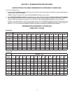
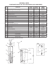
SECTION 2: INSTALLATION
Figure 3. BYPASS VALVE
Figure 1
CAUTION
CAUTION
To reduce the risk associated with property damage due to water leakage:
• Read and follow Use instructions before installation and use of this water treatment system.
• Installation and use MUST comply with existing state or local plumbing codes.
To reduce the risk associated with property damage due to plugged water lines:
• Pay particular attention to correct orientation of control valve. Water fl ow should match arrow on control valve. The Inlet and Outlet of other water treatment
equipment products will vary depending on the control valve brand used.
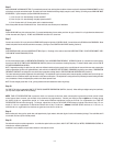
Proper installation sequence of water conditioning equipment is very important. Refer to the following diagram for your particular water supply.
Figure 2. CLAMP ASSEMBLY