5
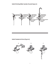
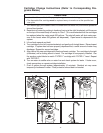
1) Install Drinking Water System Faucet (Refer to Figure 4, Page 11):
Instructions for drilling 9/16” diameter hole through counter top or stainless steel sink
A. Locateareatobedrilled.Markcenteroftheholewithcenterpunch.
B. Drillholewith9/16”drillbitsuitabletocountertopmaterialsorcastiron/stainlesssteel.
C. With grinding wheel or file, smooth out any rough edges.
Installing the Faucet
A. Slide the following parts in the order specified up blue tubing and threaded brass stem:
1. Stainless steel bezel
2. Large rubber washer
B. Next,feedbluetubingandfaucetstemdownthroughfaucetmountinghole.
C. From underneath sink, assemble the black spacer, star washer and hex nuts as shown
(see Figure 4, Page 11) onto the threaded brass stem and tighten by hand.
D. With a padded adjustable wrench, turn the faucet base (above the counter) to the right
(clockwise)tosecurelyfasten.Removepieceofplastictubingfrombase.
E. Insert faucet neck onto base until seated and align over sink.
2) Mount System
Determine undersink mounting location
A. Markholesonmountingsurfaceusingholesonbracketasguides.
B. Drillstarterholesintomountingsurface.
C. Hangunitontomountingsurfacebyfasteningwoodscrewsthroughbackplateofbracket.
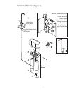
3) Install Feedwater Valve (Refer to Figure 5, Page 11)
A. Most sinks use 3/8” copper tubing. Connect the saddle valve as shown in Figure 5,
Page11.Thebacksaddlebracketcanbereversedforsmallerpipesizes(7/16”to1/2”).
Tighten screws evenly and firmly, brackets should be parallel.
To reduce the risk associated with a hazardous voltage due to an installer drilling through
existing electric wiring or water pipes in the area of installation:
•Do not install near electric wiring or piping which may be in the path of a drilling tool when
selecting the position to mount the filter bracket.
To reduce the risk associated with property damage due to water leakage:
• Shutoffcoldwatervalveunderthesinkbeforeinstallingfeedwatervalve.
• InstallationandUseMUST comply with all state and local plumbing codes.
CAUTION
WARNING
• Porcelain,enamelandceramicsinksrequirespecialproceduresfordrillingholes.Refertothe
special section on porcelain, enamel and ceramic sinks for detailed instructions.
• Thedrinkingwatersystemfaucetshouldbelocatedonaatsurface,convenientlylocatednear
thesink,sothatitemptiesintothesink.Mostsinkshavepre-drilledholesdesignatedforspray-
ers, soap dispensers and other accessories. If your sink does not have an extra hole, then a
9/16”diameterholemustbedrilled.
IMPORTANT NOTES
• Allowaminimumof2”(5cm)clearspaceunderltertofacilitatecartridgechange.
IMPORTANT NOTES


