


4 To link the access point to your Ethernet network, plug one end of another Ethernet cable into
the port labeled To Hub/Switch on the power supply, and plug the other end into a LAN port
(on a hub or in a wall).
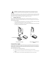
Using a Power-Over-Ethernet LAN Port
If your LAN equipment complies with the IEEE 802.3af power-over-Ethernet standard, you can connect the
access point directly to a LAN port. For example, the illustration above right shows a connection through a
3Com Ethernet Power Supply to a 3Com SuperStack
®
Switch.
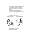
4 Check the LEDs
When power is connected, the access point LEDs light. The illustration and the following table describe the
LEDs and their functions.
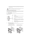
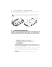
5 Wall Mount Installation
1 Install the mounting plate as shown in the following illustration, on either a stud (or other
hard wall surface), or onto drywall.
CAUTION: To avoid damaging network equipment, make sure that the cables are connected
from access point to power supply to LAN as shown and described above.
Name Description
Radio LED blinks red to indicate radio activity. Faster blinking
indicates more activity.
Power LED lights green when operational code is running.
Reset
Button
Press this button in for 15 seconds to restore the factory
defaults.
Ethernet LED lights yellow when Ethernet link is established. LED
blinks to indicate activity on the Ethernet. Faster blinking
indicates more activity.
Radio LED blinks red to indicate radio activity. Faster blinking
indicates more activity. This LED is only active when a
second radio is installed.
Reset
Button
If installing into drywall, use
3 plastic anchors and 3 screws.
If installing into a stud or other
secure vertical surface, use 2 screws.