246695-YTG-C-0708
Johnson Controls Unitary Products 15
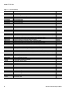
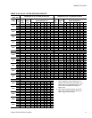
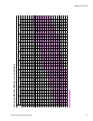
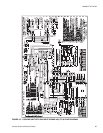
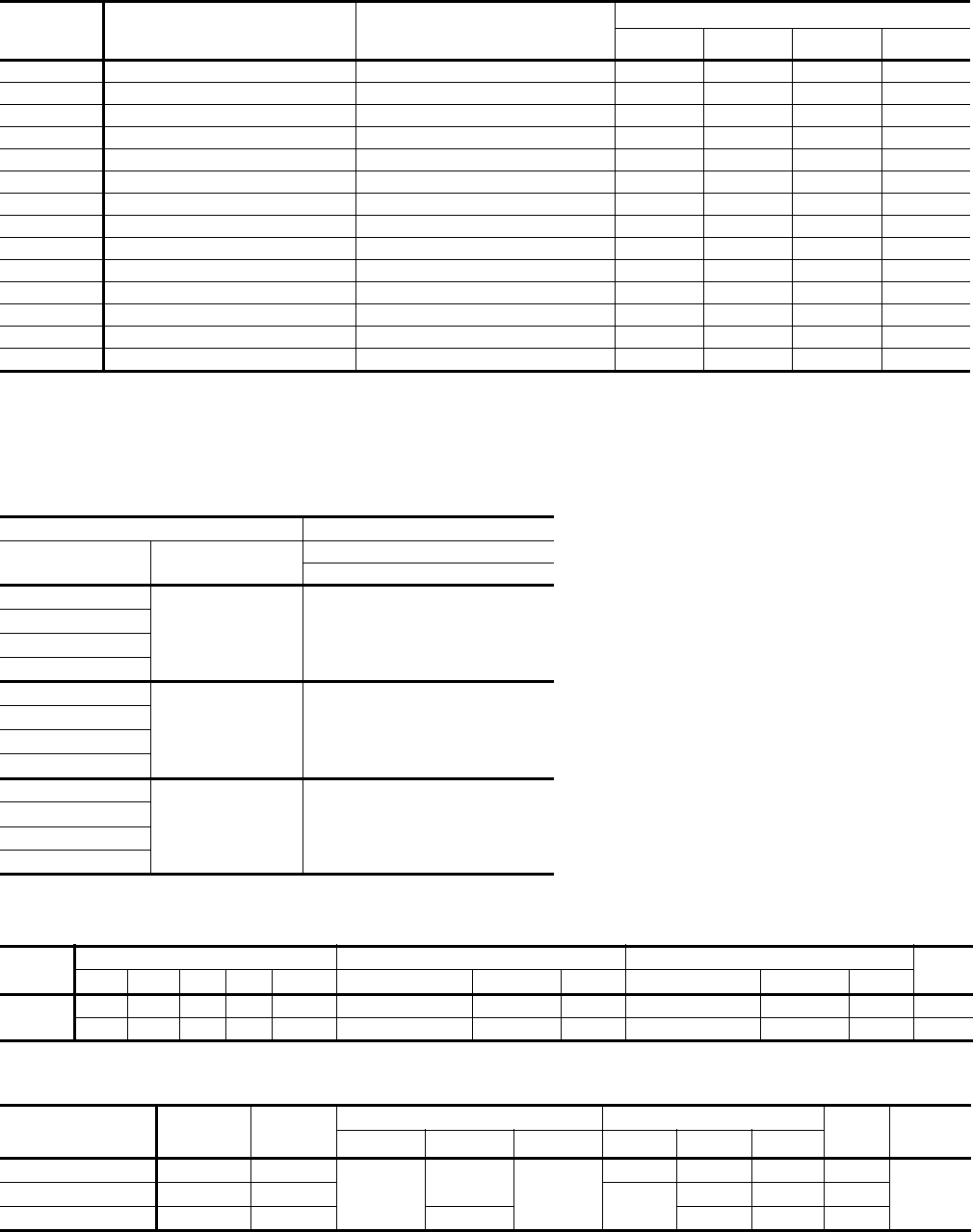
TABLE 11: ADDITIONAL STATIC RESISTANCE
CFM
Cooling Only
1
Economizer
2
3
Electric Heat KW
2
18 24 36 54
3700 0.20 0.04 0.18 0.21 0.22 0.26
3900 0.23 0.04 0.20 0.23 0.24 0.28
4100 0.25 0.04 0.22 0.25 0.26 0.31
4300 0.28 0.05 0.24 0.28 0.29 0.34
4500 0.30 0.05 0.26 0.30 0.31 0.37
4700 0.33 0.05 0.29 0.33 0.34 0.40
4900 0.36 0.05 0.31 0.35 0.37 0.43
5100 0.39 0.06 0.34 0.38 0.40 0.46
5300 0.42 0.06 0.37 0.41 0.43 0.49
5500 0.45 0.06 0.40 0.44 0.46 0.53
5700 0.48 0.06 0.43 0.47 0.49 0.56
5900 0.52 0.07 0.46 0.50 0.53 0.59
6100 0.56 0.07 0.49 0.53 0.56 0.62
6300 0.60 0.07 0.53 0.56 0.59 0.65
1 Add these resistance values to the available static resistance in the respective Blower Performance Tables.
2 Deduct these resistance values from the available external static pressure shown in the respective Blower Performance Table.
3 The pressure drop through the economizer is greater for 100% outdoor air than for 100% return air. If the resistance of the return
air duct system is less than 0.25 IWG, the unit will deliver less CFM during full economizer operation.
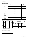
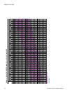
TABLE 12: ELECTRIC HEAT MINIMUM SUPPLY AIR CFM
HEATER
UNIT NOMINAL TONS
kW
VOLTAGE
12.5
MINIMUM SUPPLY AIR CFM
18
208/230 3750
24
36
54
18
480 3750
24
36
54
18
600 3750
24
36
54
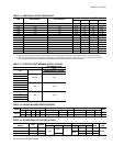
TABLE 13: INDOOR BLOWER SPECIFICATIONS
MODEL
MOTOR MOTOR SHEAVE BLOWER SHEAVE
BELT
HP RPM Eff. SF Frame Datum Dia. (in.) Bore (in.) Model Datum Dia. (in.) Bore (in.) Model
DJ150
3 1725 80% 1.15 56 3.4 - 4.4 7/8 1VM50 7.0 1 AK74 A54
5 1725 87% 1.15 184T 4.3 - 5.3 1 1/8 1VP56 6.7 1 BK77 BX55
TABLE 14: POWER EXHAUST SPECIFICATIONS
POWER EXHAUST
MODEL
VOLT PHASE
MOTOR ELECTRICAL
FUSE
SIZE
CFM@
0.1 ESP
HP
RPM
1
1 Motors are multi-tapped and factory wired for high speed.
QTY LRA FLA MCA
2PE0473125 208/230 1
0.75
1075
1
24.9 5.0 6.3 10
3,8002PE0473146 460 1
N/A
2.2 2.8 5
2PE0473158 575 1 1050 1.5 1.9 4