035-14832-003-A-0204
2 Unitary Products Group
General
................................................................................
1
Inspection
............................................................................
1
Reference
............................................................................
1
Approvals
............................................................................
1
Nomenclature
......................................................................
2
INSTALLATION
Limitations
...........................................................................
3
Location
...............................................................................
3
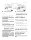
Rigging and Handling
..........................................................
3
Clearances
..........................................................................
3
Ductwork
.............................................................................
3
Filters
...................................................................................
4
Condensate Drain
...............................................................
4
Service Access
....................................................................
4
Thermostat
..........................................................................
4
Power and Control Wiring
...................................................
4
Blower Speed Selection
......................................................
4
Compressors
.......................................................................
4
Combustion Discharge
........................................................
4
Disconnect Switch Bracket For Optional Belt-Drive
............
5
Gas Piping
...........................................................................
5
Gas Connection
...................................................................
6
L.P. Units, Tanks and Piping
................................................
6
Low NOx Application
...........................................................
6
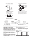
Vent and Combustion Air Hoods
.........................................
7
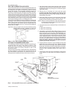
Optional Economizer Rain Hood
.........................................
7
OPERATION
Cooling System .................................................................13
Preliminary Operation Cooling ..........................................13
Cooling Sequence of Operation ........................................13
Safety Controls (Cooling) ..................................................13
Heating Sequence of Operation........................................13
Safety Controls (Heating)................................................. 14
Heat Anticipator Setpoints.................................................14
Pre-Start Check List ..........................................................14
START-UP
Operating Instructions
.......................................................
14
Post-Start Check List (Gas)
...............................................
14
Manifold Gas Pressure Adjustment
...................................
14
Pilot Checkout
...................................................................
15
Burner Instructions
............................................................
15
Burner Air Shutter Adjustment
...........................................
15
Supply Air Blower and Temperature Rise Adj.
...................
15
Supply Air Blower and Temperature Rise Adj.
............
15&16
Checking Gas Input
...........................................................
16
Secure Owner's Approval
..................................................
16
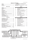
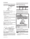
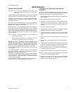
D 2 E G 4N
PRODUCT NOMENCLATURE
PRODUCT GENERATION
2 = 2nd Generation
3 = 3rd Generation
PRODUCT CATEGORY
D = Single Package Air Conditioner
(Air Cooled)
PRODUCT IDENTIFIER
EG = High Efficiency Gas/Electric
VOLTAGE CODE
06 = 208/230-1-60
25 = 208/230-3-60
46 = 460-3-60
58 = 575-3-60
NOMINAL GAS HEATING
OUTPUT CAPACITY
036 = 3 Ton
048 = 4 Ton
060 = 5 Ton
0 030 6 2 5
FACTORY INSTALLED HEAT
N = Natural Gas
NOMINAL COOLING
CAPACITY
040 = 40 MBH
060 = 60 MBH
079 = 79 MBH
099 = 99 MBH
MAINTENANCE & TROUBLESHOOTING
Normal Maintenance
.........................................................
17
Cleaning Flue Passages and Heating Elements
...............
17
Troubleshooting
........................................................
18 & 19
TABLES
No. Description Page
1 Unit Application Data
..................................
3
2 Gas Heat Application Data
.........................
4
3 Pipe Sizing
.................................................
5
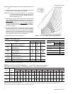
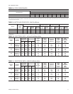
4 Physical Data
.............................................
8
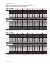
5 Supply Air Perf. Direct-Drive Units
............
8
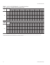
6 Supply Air Perf.3 & 4Ton Belt-Drive Units
..
9
7 Supply Air Perf.5 Ton Belt-Drive Units
.......
10
8 Static Resistances
......................................
11
9 Motor & Drive Data
.....................................
11
10 Electrical Data (Direct-Drive Units)
............
11
11 Electrical Data (Belt-Drive Units)
................
11
12 Limit Control Setting
...................................
14
13 Belt-Drive Supply Air Motor Pulley Adj.
......
15
14 Gas Rate - Cubic Feet Per Hour
................
16
FIGURES
No. Description Page
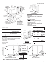
1 Center of Gravity........................................ 3
2 Recommended Drain Piping...................... 4
3 Typical Field Wiring.................................... 5
4 External Supply Connection....................... 6
5 Bottom Supply Connection......................... 6
6 Vent and Combustion Air Hoods................ 7
7 Economizer Rain Hood Assembly.............. 7
8 Enthalpy Setpoint Adjustment.................... 8
9 Dimensions and Clearances...................... 12
10 Gas Valve Piping
........................................
13
11 Typical Gas Valve
.......................................
14
12 Proper Flame Adjustment
..........................
15
13 Typical Flame Appearance
.........................
15
14 Belt Adjustment
..........................................
15
15 Press. Drop versus Supply Air CFM
..........
16
TABLE OF CONTENTS