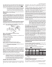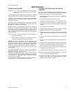
PILOT CHECKOUT
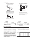
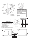
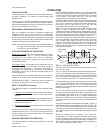
The pilot flame should envelope 3/8 inches of the end of the
flame sensor. Refer to Figure 12. To adjust pilot flame, (1)
remove pilot adjustment cover screw, (2) adjust the screw for
the proper pilot flame, (3) be sure to replace cover screw
after
adjustment to prevent possible gas leakage.
Put the system into operation and observe through complete
cycle to be sure all controls function properly.
BURNER INSTRUCTIONS
To check or change burners, pilot or orifices, CLOSE MAIN
MANUAL SHUT-OFF VALVE AND SHUT OFF ALL POWER
TO THE UNIT.
1. Remove the two screws holding either end of the manifold
to the burner supports.
2. Openthe unionfitting inthe gassupply linejust upstreamof
the unit gas valve and downstream from the main manual
shut-off valve.
3. Remove the gas piping patch plate.
4. Disconnect wiring to the gas valve and spark ignitor.
Remove the manifold-burner gas valve assembly by lifting
up and pulling back.
Burners are now accessible for service.
Reverse the above procedure to replace the assembly. Make
sure that burners are level and seat at the rear of the heat
exchanger.
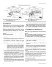
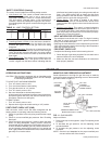
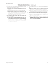
BURNER AIR SHUTTER ADJUSTMENT
Adjust burner shutters so that a distinct, sharp, blue flame is
obtained. Refer to Figure 13.
SUPPLY AIR AIR BLOWER AND TEMPERATURE
RISE ADJUSTMENTS
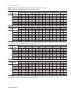
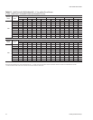
The speed of the supply air blower will depend on the required
CFM,the unitaccessories andthe staticresistancesof boththe
supply and the return air duct systems. With this information,
the speed for the supply air blower canbe determined from the
blower performance and accessory static resistance data in
Table 5 through 8.
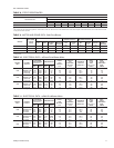
Knowing the required blower RPM and the blower motor HP,
the speed setting for the supply air motor can be determined.
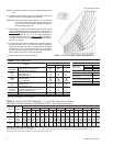
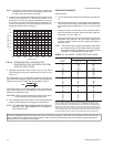
The setting (turns open) for the optional belt-drive supply air
motor pulley can be determined from Table 13.
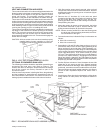
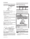
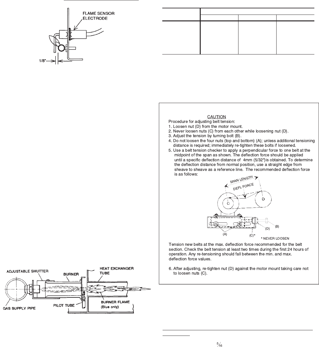
OPTIONAL BELT-DRIVE BLOWER
All units with belt-driveblowers have single speed motors. The
variable pitch pulley on the blower motor can be adjusted to
obtain the desired supply air CFM. Refer to Table 9 for blower
motor and drive data. The tension on the belts should be
adjusted as shown in Figure 14.
Startthe supplyair blowermotor.Adjust theresistances inboth
the supply and the return air duct systems to balance the air
distribution throughout the conditioned space. The job
specifications may require that this balancing be done by
someone other than the equipment installer.
Tocheck thesupply airCFMafter theinitial balancinghasbeen
completed:
1. Remove the (two) " dot plugs from the holes located on
the filter access panel side of the unit.
2. Insert at least 8" of 1/4 inch tubing into each of these holes
for sufficient penetration into the air flow on both sides of
the evaporator coil.
Unitary Products Group 15
035-14832-003-A-0204
FIG. 12 - PROPER FLAME ADJUSTMENT
FIG. 13 - TYPICAL FLAME APPEARANCE
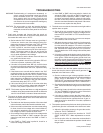
TURNS
OPEN*
BLOWER DRIVE RANGE (RPM)
3 TON 4 TON 5 TON
5
4
3
2
1
0
780
842
904
966
1028
1090
790
856
922
988
1054
1120
850
924
998
1072
1246
1220
*Pulley can be adjusted in half-turn increments.
TABLE 13 - BELT-DRIVE SUPPLY AIR
MOTOR PULLEY ADJUSTMENT
FIG. 14 - BELT ADJUSTMENT