Please Do Not Return This Product To The Store. Contact your local Wayne-Dalton dealer. To find your local Wayne-Dalton dealer,
refer to your local yellow pages business listings or go to the Find a Dealer section online at www.Wayne-Dalton.com
side.
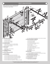
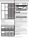
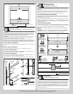
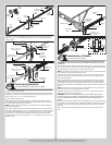
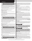
IMPORTANT: THE DIMENSION BETWEEN THE FLAG ANGLES MUST BE:
FOR 2” TRACK APPLICATIONS: DOOR WIDTH PLUS 3-3/8” (86MM) TO 3-1/2” (89 MM) FOR
SMOOTH, SAFE DOOR OPERATION.
FOR 3” TRACK APPLICATIONS: DOOR WIDTH PLUS 4-7/8” (124MM) TO 5” (127 MM) FOR
SMOOTH, SAFE DOOR OPERATION.
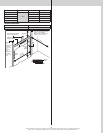
Complete the vertical track installation by securing the jamb bracket(s) or slots in the wall
angle and tightening the other lag screws. Push the vertical track against the track rollers so
that the track rollers are touching the deepest part of the curved side of the track; tighten all
the track bolts and nuts. Repeat for other side.
Top section
Top
section
Nail
Flag angle or
wallangle assembly
Top of flag angle or
Top of wallangle assembly
Vertical track
against rollers
Door width (2” Track)
+ 3-3/8” to 3-1/2”
Door width (3” Track)
+ 4-7/8” to 5”
2” Track Applications:
1-11/16” to 1-3/4”
3” Track Applications:
2-3/16” to 2-1/4”
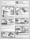
Horizontal Tracks
Tools: Ratchet wrench, 7/16” Socket, 9/16” Socket, 9/16” Wrench,
15
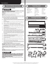
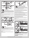
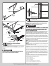
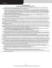
To install horizontal track, place the curved end over the top track roller of the top section.
Align the bottom rail of the horizontal track with the top of the vertical track. Tighten the bot-
tom rail of the horizontal track to the flag angle or wall angle with (2) 1/4”-20 x 9/16” track
bolts and (2) 1/4”-20 flange hex nuts.
Flag angle
(2) 1/4”-20 x 9/16”
Track bolts
(2) 1/4”-20
Flange hex nuts
Bottom rail of
horizontal track
Vertical
track
Wall angle
(2) 1/4”-20 x 9/16”
Track bolts
(2) 1/4”-20
Flange hex nuts
Vertical
track
Bottom rail of
horizontal track
WARNING WARNING
DO NOT RAISE DOOR UNTIL HORIZONTAL TRACKS ARE SECURED AT REAR,
AS OUTLINED IN STEP, REAR BACK HANGS, OR DOOR COULD FALL FROM
OVERHEAD POSITION CAUSING SEVERE OR FATAL INJURY.
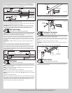
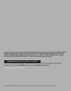
Level the horizontal track assembly.
For riveted track assembly, bolt the top rail of the horizontal track to the first encountered slot
in the flag angle using (1) 1/4”-20 x 9/16” track bolt, (1) washer and (1) 1/4”-20 flange hex
nut.
For wall angle track assembly, first bolt the angle of the horizontal track to the slots in the
wall angle using (2) 3/8”-16 x 3/4” truss head bolts and (2) 3/8”-16 hex nuts. Now secure
the top rail of the horizontal track to the wall angle using (1) 1/4”-20 x 9/16” track bolt, (1)
washer and (1) 1/4”-20 flange hex nut.
Repeat for other side.
Remove the nail that was temporarily holding the top section in place, installed in step, Top
Section.
IMPORTANT: FAILURE TO REMOVE NAIL BEFORE ATTEMPTING TO RAISE DOOR COULD
CAUSE PERMANENT DAMAGE TO TOP SECTION.
Flag angle
(2) 3/8”-16 x 3/4”
Truss head bolts
Top rail of
horizontal track
Wall angle
Washer
(1) 1/4”-20 Flange hex nut
(1) 1/4”-20 x 9/16”
Track bolt
Washer
(1) 1/4”-20
Flange hex nut
(1) 1/4”-20 x 9/16”
Track bolt
Top rail of
horizontal track
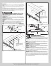
Adjusting Top Fixtures
Tools: 7/16” Wrench, Step ladder
16
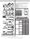
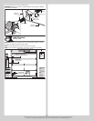
With horizontal tracks installed, you can now adjust the top fixtures.
NOTE: If your door came with two top fixtures, then one top fixture is required to be adjusted
for each side.
NOTE: If your door came with four top fixtures, then two top fixtures are required to be
adjusted for each side.
Starting on the left hand side, vertically align the top section of the door with the lower sec-
tions. Maintaining the top fixture(s) position, tighten the 1/4”-20 flange hex nuts or 1/4”-20
x 1-3/8” bolts and or 1/4”-14 x 1” lag screws to secure the top fixture(s) to the top section.
Repeat for other side
Left hand top fixture(s)
Track roller
(2) 1/4” - 20 Flange hex nuts or
(2) 1/4” - 20 x 1-3/8” bolts
Horizontal
tracks
Top section
Top
rail
(2) 1/4” - 14 x 1”
Lag screws
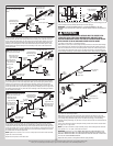
Cable Lift Sheaves
Tools: Ratchet Wrench, 3/8” Socket, 3/8” Wrench
17
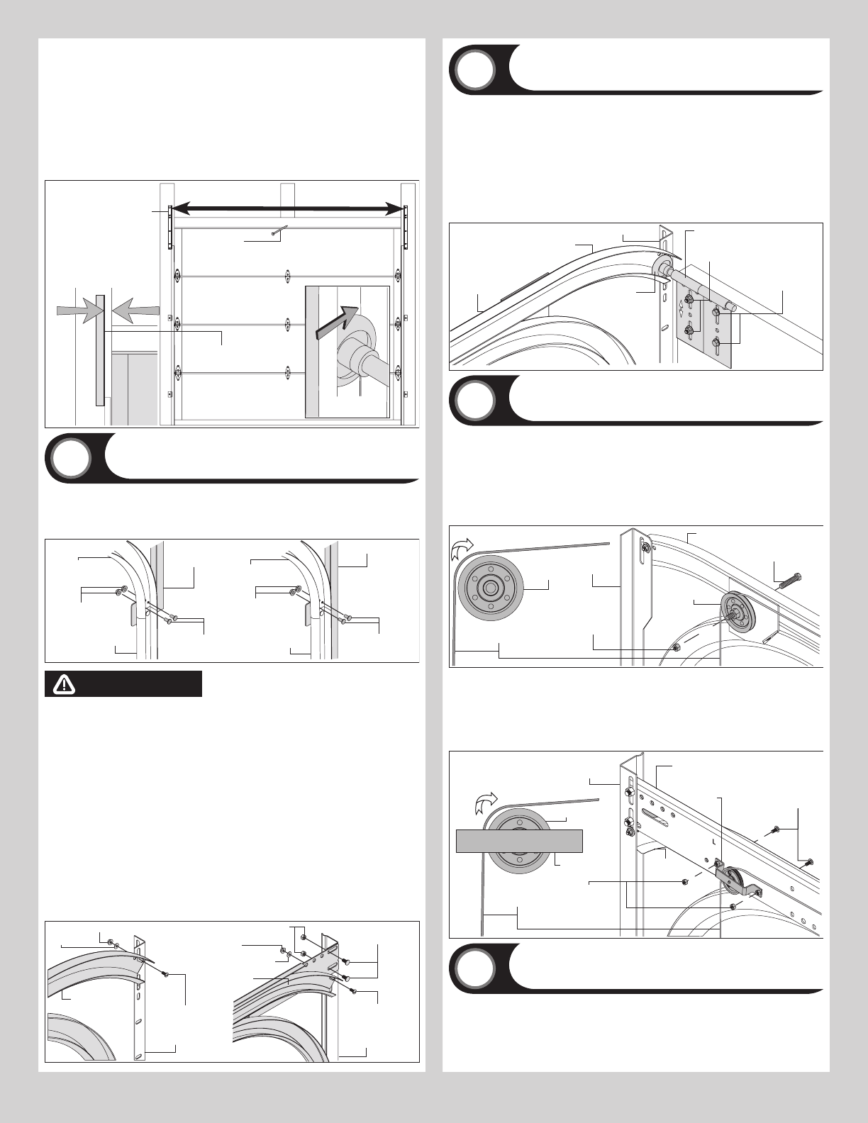
Using the illustrations below, identify which cable lift sheave assemblies were provided with
your door.
For Cable Sheave Assemblies without Sheave Saddle:
Place a 3/8”-16 x 1-1/2” hex head bolt through the hole in the sheave plate. Next insert the
sheave over the end of the bolt. Secure the sheave to the sheave plate with a 3/8”-16 nut.
Repeat the same process for the other side. Then loop the counterbalance cables over each
sheave, as shown.
(1) 3/8” - 16 X 1-1/2”
Hex head bolt
Sheave
Counterbalance
lift cable
(1) 3/8” - 16
Nut
Sheave plate
Typical
flagangle
Horizontal track
For Cable Sheave Assemblies With Sheave Saddle:
Position the sheave saddle over the 1” x 4” x 23” angle and align the slots in the sheave
saddle with the corresponding holes in the 1” x 4” x 23” angle. While holding the sheave
saddle in place, insert (1) 5/16”-18 x 3/4” square neck carriage bolt through each of the
aligned holes and secure the assembly with 5/16-18 hex nuts. Repeat the same process for
the other side. Then loop the counterbalance cables over each sheave, as shown.
(2) 3/8” - 18 X 3/4”
Square neck carriage
bolts
Sheave
Counterbalance
lift cable
(2) 5/16” - 18
Hex nuts
Sheave
saddle
Typical
wall angle
Horizontal
track
1” x 4” x 23”
Angle
Sheave
saddle
Rear Back Hangs
Tools: Ratchet Wrench, 1/2” Socket, Tape Measure , 1/2” Wrench, Vice
18
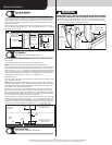
Using perforated angles, 1-5/8” lag screws and 5/16” bolts with nuts, fabricate rear back
hangs for horizontal tracks. NOTE: These items may not have been supplied. Attach horizon-
tal tracks to the rear back hangs with two 5/16”-18 x 1” hex head bolts and nuts. Horizontal
tracks must be level and parallel with door.
NOTE: Ensure the two 5/16”-18 x 1” hex head bolts are going through the vertical piece
11