-
10 -
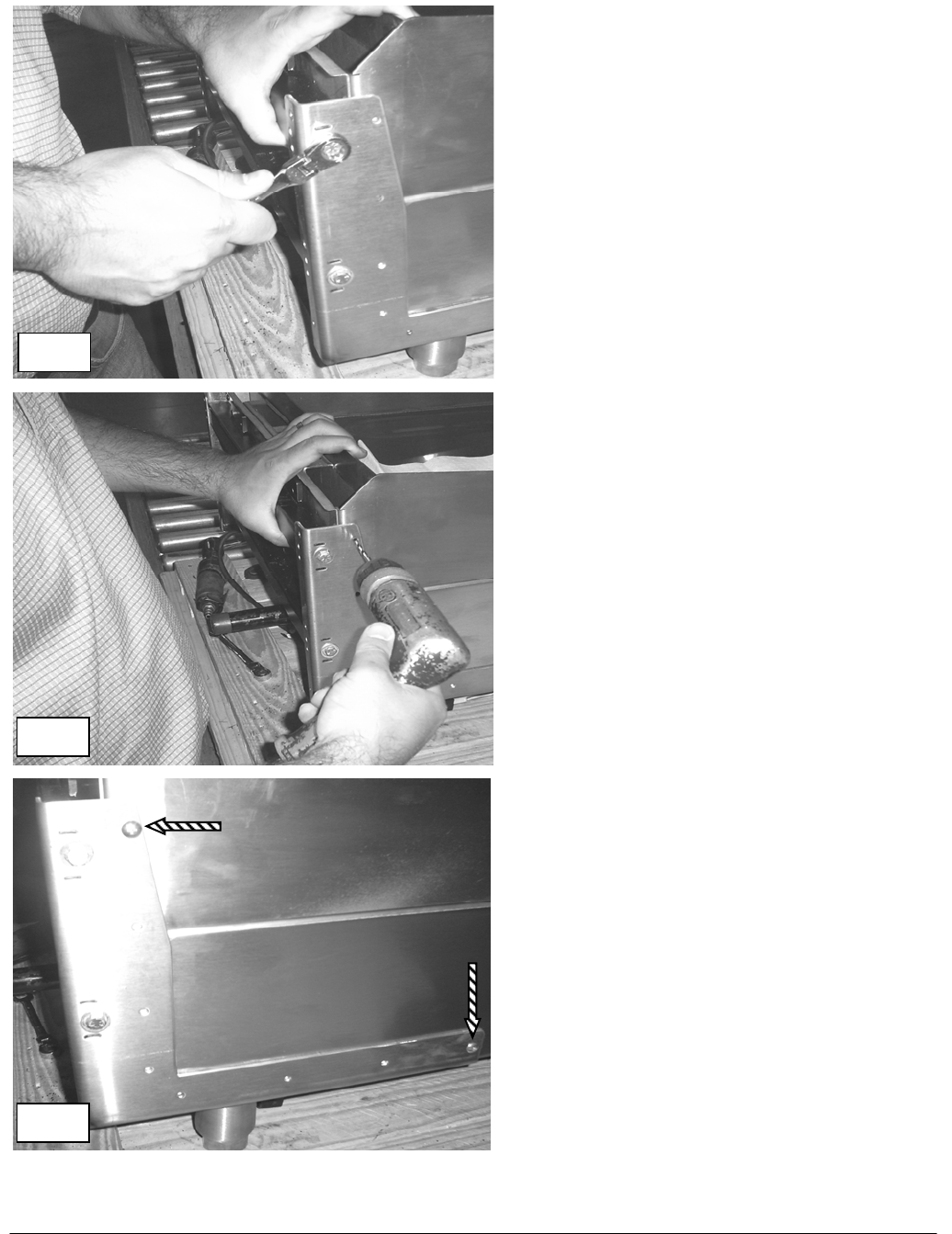
4. Securely tighten the mounting bracket
system assembly bolts at the left and
right side mounting brackets.
Fig. 4.
5. Check that the left and right mounting
brackets have not moved from position
while the assembly bolts were
tightened. The “F” clamps should still
be in place to prevent the assembly
from moving while drilling holes in the
chassis.
Check before drilling holes in chassis, it
is important that the assembly has not
moved from the location prescribed in
step # 3
6. Using the side mounting bracket as a
guide, drill holes into the griddle chassis
with the 5/32” bits only at the highest
hole and the hole nearest the front of
the unit on the side bracket. See Fig. 5
and Fig 6. Repeat procedure for
opposite side of bracket system
assembly.
7. Insert and tighten 10-24 x ½ screws into
the holes that were drilled in step 6.
Repeat procedure for opposite side of
bracket system assembly. See Fig. 6.
Fig. 4
Fig. 5
Fig. 6
