11
Status Request Commands
DEVICE TYPE REQUEST (8FH)
Requests the information on the type of equipment
controlled. The device type is a unique code assigned
to each model to distinguish it from other models. The
device type of the HSR-1/1P is A0H.
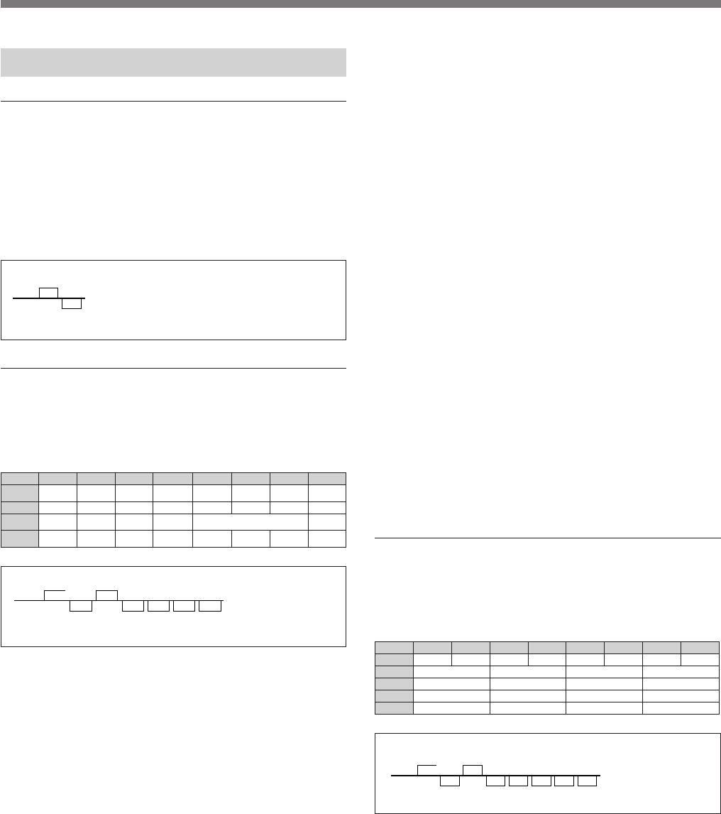
Example: With HSR-1/1P:
STATUS SENSE (DAH+C0H)
Requests the return of VTR status data. When this
command is issued, the VTR returns four-byte status
data, as shown below.
7tib 6tib 5tib 4tib 3tib 2tib 1tib 0tib
1etyb 100
CER
TIBIHNI
ETTESSAC
TUO
MRALA0RORRE
2etybESUAP0HCRAESYALPWERDWF.FPOTSTCEJE
3etyb0
REMIT
CER
TAEPER
CER
-UNITNOC
CERSUO
CERMRALACER
4etybVER/DWF0000
MRALA
HCRAES
D/T
HCRAES
DEVRESER
First byte
bit 4: Becomes 1 when a record inhibited tape is
inserted.
bit 3: Becomes 1 when a cassette is not loaded into
the VTR.
bit 2: Becomes 1 when an alarm occurs is generated.
bit 0: Becomes 1 when an error occurs.
Second byte
bit 7: Becomes 1 when the VTR is in Pause mode.
bit 5: Becomes 1 when the VTR is in Search mode.
bit 4: Becomes 1 when the VTR is in Play mode.
bit 3: Becomes 1 when the VTR is in Rewind mode.
bit 2: Becomes 1 when the VTR is in Fast forward
mode.
bit 1: Becomes 1 when the VTR is in Stop mode.
bit 0: Becomes 1 while the VTR is ejecting the
cassette.
Third byte
bit 6:
0: No timer setting
1: Timer On
bit 5: Becomes 1 when Repeat recording is on.
bit 4: Becomes 1 when Continuous recording is on.
bits 3, 2 and 1:
000: No alarm recording setting
001: Alarm recording in Normal mode is on.
010: Alarm recording in Interleave mode is on.
011: Alarm recording in Event mode is on.
100: Alarm recording in Pre-alarm mode is on.
101: Alarm recording in Frame mode is on.
bit 0: Becomes 1 when the VTR is recording.
Fourth byte
bit 7: Shows the search direction when the VTR is in
Search mode.
0: FWD
1: REV
bit 2: Becomes 1 while the VTR is executing the
ALARM SEARCH (DAH+97H) command.
bit 1: Becomes 1 while the VTR is executing the T/D
SEARCH (DAH+96H) command.
bit 0: Reserved
CAMERA SENSE (DAH+C2H)
Requests the status of camera connections and video
signal inputs. When this command is issued, the VTR
returns the five-byte status data shown below.
7tib 6tib 5tib 4tib 3tib 2tib 1tib 0tib
1etyb 10000000
2etyb4AREMAC3AREMAC2AREMAC1AREMAC
3etyb8AREMAC7AREMAC6AREMAC5AREMAC
4etyb21AREMAC11AREMAC01AREMAC9AREMAC
5etyb61AREMAC51AREMAC41AREMAC31AREMAC
Second to fifth bytes
Each two bits show the status of the corresponding
camera.
00: NO CONNECT
10: No signal input
11: Signal being input
RxD
TxD
8FH
A0H
CMD
DEVICE TYPE
RxD
TxD
DAH
0AH
C7H
xxH xxH xxH
xxH
EXP-3 CMD
ACK DATA DATA DATA DATA
RxD
TxD
DAH
0AH
C2H
80H xxH xxH xxH xxH
EXP-3 CMD
ACK DATA DATA DATA DATA DATA


