ENGINE THROTTLE ADJUSTMENT TEST PROCEDURE (CONTINUED)
PROCEDURE
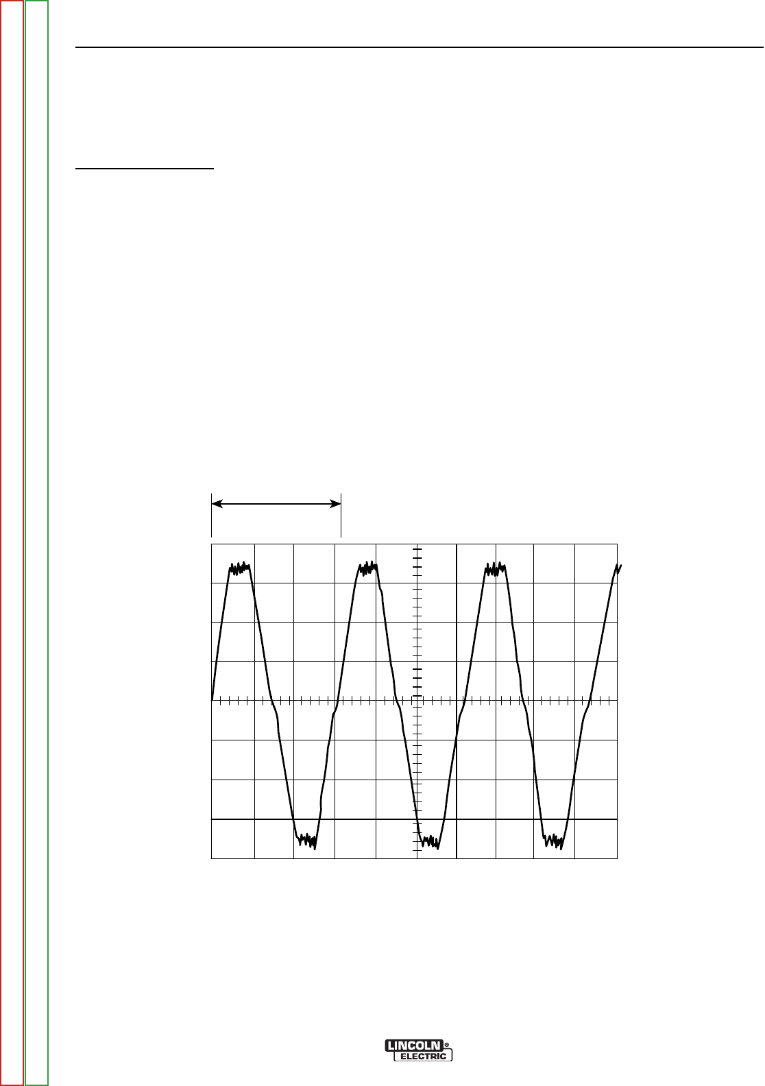
Oscilloscope Method
1. Connect the oscilloscope to the 115 VAC recepta-
cle, according to the manufacturer’s instructions.
At HIGH IDLE (1900 RPM), the waveform should
exhibit a period of 15.8 milliseconds. At LOW IDLE
(1475 RPM), the waveform should exhibit a period
of 20.3 milliseconds. Refer to the NORMAL OPEN
CIRCUIT VOLTAGE WAVEFORM (115 VAC SUP-
PLY) HIGH IDLE - NO LOAD below.
2. If either of these waveform periods is incorrect,
adjust the throttle as follows:
Adjust HIGH IDLE: Use the 10mm wrench to
loosen the locking nut. See Figure F.7 for location
of the adjusting screw and locking nut. Turn the
threaded screw counter-clockwise to increase the
HIGH IDLE speed. Adjust the speed until the peri-
od is 15.8 milliseconds. Retighten the locking nut.
Adjust LOW IDLE: First make sure there is no load
on the machine. Set the IDLE switch to AUTO and
wait for the engine to change to low idle speed.
Use the 10mm wrench to loosen the solenoid lever
arm locking nut. See Figure F.7 Adjust the collar,
to change the amount of throw in the lever arm,
until the period is 20.3 milliseconds. Retighten the
locking nut.
TROUBLESHOOTING AND REPAIR
F-28 F-28
VANTAGE® 500
This is the typical auxiliary output voltage generated from a properly operating
machine.
Note that each vertical division represents 50 volts and that each horizontal divi-
sion represents 5 milliseconds in time.
Note: Scope probes are connected at machine 115VAC receptacle.
NORMAL OPEN CIRCUIT VOLTAGE WAVEFORM (115VAC SUPPLY)
HIGH IDLE – NO LOAD
Return to Section TOC Return to Section TOC Return to Section TOC Return to Section TOC
Return to Master TOC Return to Master TOC Return to Master TOC Return to Master TOC


