16
LENNOX HEARTH PRODUCTS • MONTEBELLO
®
POWER VENT DV GAS FIREPLACES (LSM40/45EN-PV) • CARE AND OPERATION INSTRUCTIONS
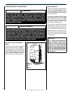
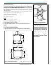
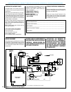
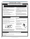
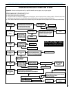
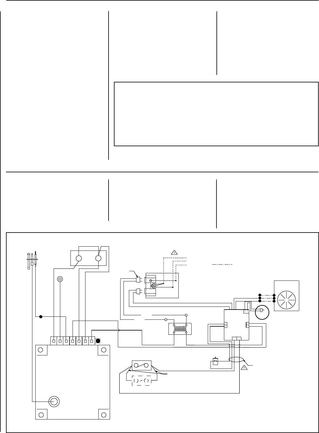
Figure 17 - Electronic Wiring Diagram
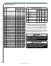
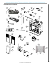
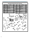
ORDERING REPLACEMENT PARTS
A complete parts list is found at the end of
this manual. Use only parts supplied from the
manufacturer.
With proper care and maintenance, your appli-
ance will provide many years of enjoyment. If
you should experience any problem, first refer
to the troubleshooting guide in this manual. If
problem persists, contact your Lennox Hearth
Products dealer or distributor.
Normally, all parts should be ordered through
your Lennox Hearth Products distributor or
dealer. Parts will be shipped at prevailing prices
at time of order.
When ordering repair parts, always give the
following information:
1. The model number of the appliance.
2. The serial number of the appliance.
3. The part number.
4. The description of the part.
5. The quantity required.
6. The installation date of the appliance.
Fireplace Model Number ________________________________________________
Fireplace Serial Number _________________________________________________
Date Installed _________________________________________________________
Type of Gas Used in Fireplace ____________________________________________
Dealer Name _________________________________________________________
If you encounter any problems or have any
questions concerning the installation or ap-
plication of this system, please contact your
dealer or distributor.
LENNOX HEARTH PRODUCTS
1508 Elm Hill Pike, Suite 108
Nashville, TN 37210
visit us at www.Lennox.com
1-800-9-LENNOX
PRODUCT REFERENCE INFORMATION
We recommend that you record the important
reference information about your fireplace in
the space provided below.
Please call Lennox Hearth Products for the
phone number of your nearest Lennox Hearth
Products dealer who will answer your questions
or address your concerns.
N/A
Black
Black (16)
Black
Black
24 V.
Pressure
Switch
Transformer
120 V.
White
Ground
Junction Box
Field Installed
Exhaust
Blower
120 VAC
Blower
(Field Installed)
To Igniter
Module
Exhaust
Blower
Control
Module
Appliance Mounted
On/Off Switch
Electronic Ignition
Control Board
Green LED
White (6)
Black (20)
Blue (20)
Red
Red
Ground
White (6)
Gas Valve
Item 45
Wire #2
Item 63
EV2 EV1
Item 32 Wire #3
Wall-Mounted On/Off Switch (optional)
Connector
Pilot Burner
Igniter-Sensor
Assembly
Orange (20)
Green (12)
Purple (9)
White (20)
Black
White
WIRING DIAGRAMS
Wiring diagrams are provided here for reference
purposes only. This information is also provided
on schematics attached directly to the appliance
on a pullout panel located within the control
compartment.
CAUTION: LABEL ALL WIRES PRIOR TO
DISCONNECTION WHEN SERVICING
CONTROLS. WIRING ERRORS CAN
CAUSE IMPROPER AND DANGEROUS
APPLIANCE OPERATION.
ATTENTION: AU MOMENT DE
L'ENTRETIEN DES COMMANDES,
ÉTIQUETEZ TOUS LES FILS AVANT DE
LES DÉBRANCHER. DES ERREURS
DE CÁBLAGE PEU-VENT ENTRAÎNER
UN FONCTIONNEMENT INADÉQUAT
ET DANGEREUX.
NOTE: DIAGRAMS & ILLUSTRATIONS ARE NOT TO SCALE.