NOTE: DIAGRAMS & ILLUSTRATIONS NOT TO SCALE.
6
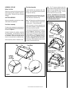
Figure 8
Figure 10
UNIT INSTALLATION
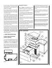
1. Prepare the framed opening as illustrated in
Framing Specification
on page 4. The header
location is important. Verify the minimum
distance before starting the installation.
2. Locate the main electrical connection on the
left side of the fireplace and connect it to the
outlet installed during the framing. Verify that
the power to the receptacle is off.
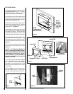
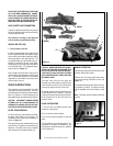
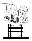
3. Lift and slide the unit into the opening until
the face is flush up against the wall. Secure the
unit to the side framing members with 1"
drywall screws. See
Figure 8
.
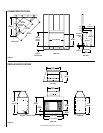
4. Install the dust cover assembly into the top
of the fireplace from the underside until the
unit snaps into position. Fold out the tabs
around the base to support it in position. This
must be done before the television is installed.
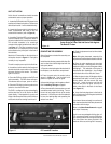
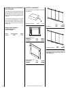
5. Hook the television assembly onto the screen
rod pins and let the unit hang in position. Plug
the television power cord into the top recep-
tacle routing behind the television latch (
see
Figure 9
).
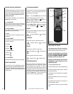
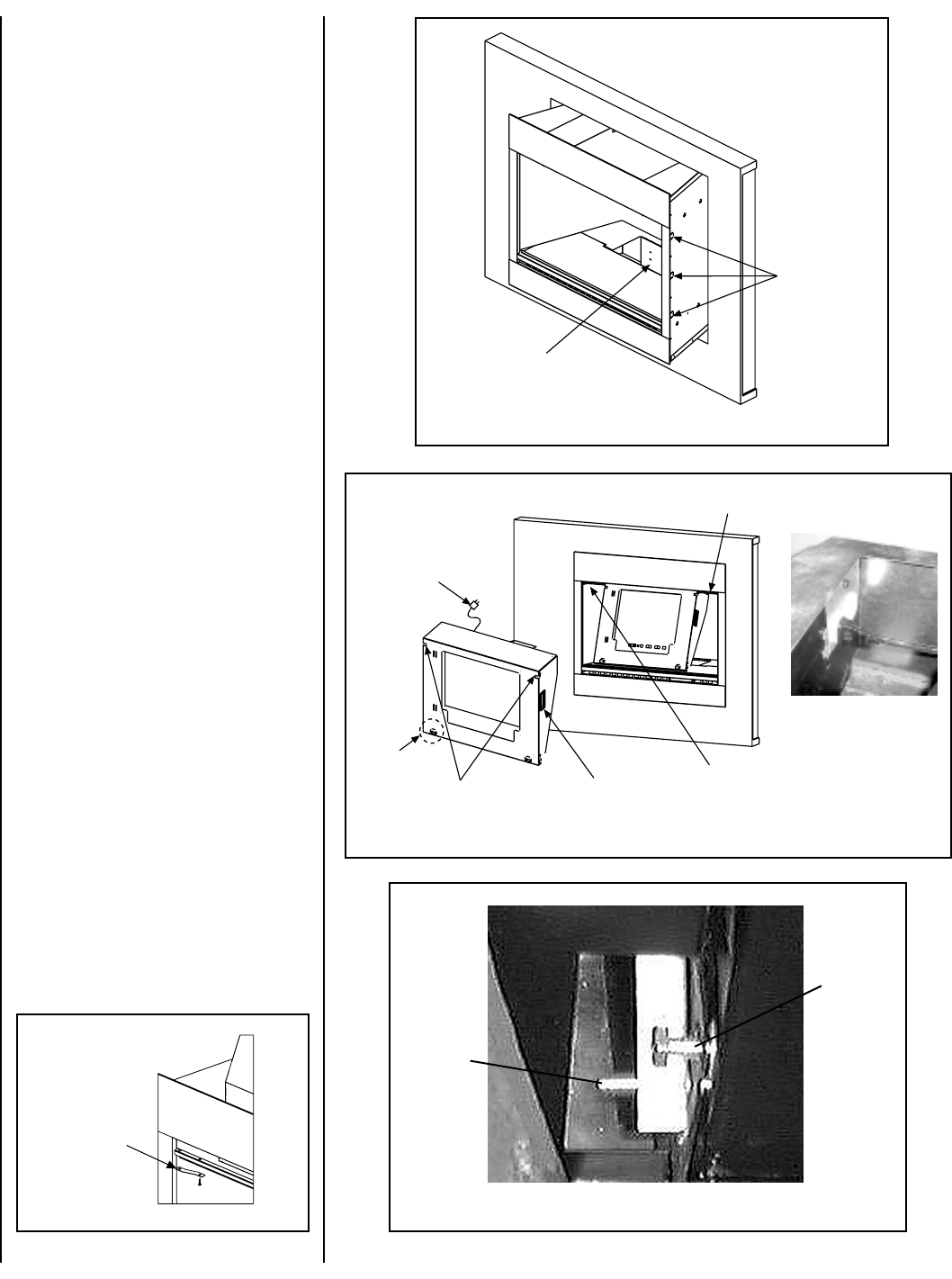
6. The television assembly will rotate up into
the unit and lock onto the latch rod.
See
Figure 10
.
CAUTION: THE TELEVISION ASSEMBLY IS
HEAVY. PLEASE CLEAR THE AREA IN FRONT
OF THE FIREPLACE BEFORE ATTEMPTING TO
SWING THE UNIT INTO POSITION. THE UNIT
MUST SWING SLIGHTLY PAST HORIZONTAL
TO LATCH. WE SUGGEST THAT TWO PEOPLE
PERFORM THIS STEP.
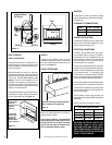
7. Two locking screws have been provided to
secure the television assembly after installa-
tion. Locate the two slots in the assembly
immediately in front of the latching rod. Hand
tighten the screws completely into the inserts
on both sides.
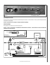
8. Refer to
Figure 7
for the location of the door
track and install at this time. Two door clips
have been provided with these instructions.
Figure 9
Screen Rod
Hand Holds
Engagement Hooks
Top Receptacle
Power Cord
Tabs
Detail Of
Top Receptacle
Locking
Screw
Latch
Rod
Figure 7
Door
Track
Secure
At These
Three (3)
Locations
From The
Inside
Ember
Compartment
Bulb And Socket