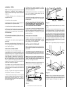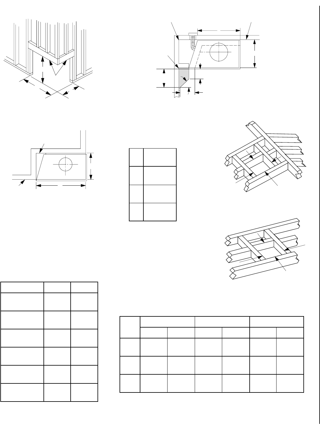
NOTE: DIAGRAMS & ILLUSTRATIONS NOT TO SCALE.
7
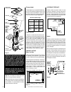
FRAMING SPECIFICATIONS
Figure 15
Figure 14
Figure 12
Figure 13
Figure 16
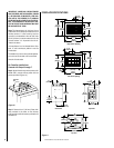
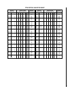
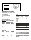
Framing Dimensions for Ceiling
Flue Type A B
FTF8 Vertical 16 ¹⁄₂" 16 ¹⁄₂"
at 2" (419 mm) (419 mm)
FTF10 Vertical 17" 17"
at 1" (432 mm) (432 mm)
FTF10 Vertical 19" 19"
at 2" (483 mm) (483 mm)
FTF8 Offset 30° 16 ¹⁄₂" 27"
at 2" (419 mm) (686 mm)
FTF10 Offset 30° 17" 26"
at 1" (432 mm) (660 mm)
FTF10 Offset 30° 19" 28"
At 2" (438 mm) (711 mm)
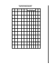
Framing Dimensions for Roof
Pitch FTF8 at 2" FTF10 at 1" FTF10 at 2"
CD*CD*CD*
0/12 16 ¹⁄₂" 16 ¹⁄₂" 17" 17" 19" 19"
(419 mm) (419mm) (432 mm) (432 mm) (483 mm) (483 mm)
6/12 16 ¹⁄₂" 19" 17" 19" 19" 21"
(419 mm) (483 mm) (432 mm) (483 mm) (483 mm) (533 mm)
12 /12 16 ¹⁄₂" 23 ¹⁄₂" 17" 24" 19" 26"
(419mm) (597mm) (432mm) (610 mm) (483mm) (660 mm)
*Perpendicular to roof ridge
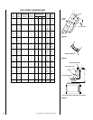
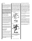
A
B
Ceiling Framing
C
D
Roof Framing
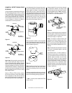
Framing Without False Header
Header
B
A
C
Outside Corner
C
A
Back Wall of Chase/Encloslure
Including Finishing
Materials if any
Rough Framing
Face (Unfinished
Shown)
Note: All framing dimensions calculated for 5/8"
nailing flange depth and 1/2" dry wall at the
fireplace face. If sheathing the chase or finishing
with other thickness materials, calculations will
need to be made.
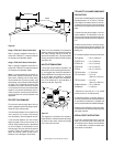
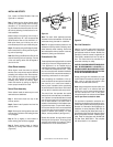
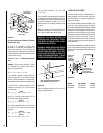
Framing Dimensions
CR-3835 Series
A 42 ⁵₈"
(1082 mm)
B 40 ⁵₈"
(1032 mm)
C 24"
(610 mm)
D 34 ⁷₈"
(886 mm)
11 ⁷⁄₈"
(302mm)
45°
8" Max.
(203mm)
8" (203mm) Min. To
Protected Side Wall
Inside Corner Using Outside Air
Note: Combustible Materials
May Be Placed In Shaded Area.
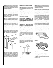
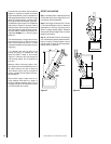
C
D
Note: No Wall Shield
Required On This Wall
Back Wall of Chase/Encloslure Including
Finishing Materials if any
Rough
Framing
Face
(Unfinished
Shown)