555 Dawson Drive, Camarillo, CA 93012 Phone 805-482-6913 • Fax 805-482-7422
6
Rev F
6/08
No.1208-1351
A Division of Thiessen Products, INC
IInnssttrruuccttiioonn SShheeeett FFoorr BBooxx 11 112200”” OOrr 113311””
EEnnggiinnee AAsssseemmbblliieess OOrr EEnnggiinnee RRaaccee KKiittss
STEP 1: Preparation
• Inspect the entire surface of the studs for damage. See Fig.5
• Minor scratches are okay in the body of the stud.
• The threaded portion of the studs must not have deformities that stud
would cause binding between the cases or head bolts.
• Set aside and cover.
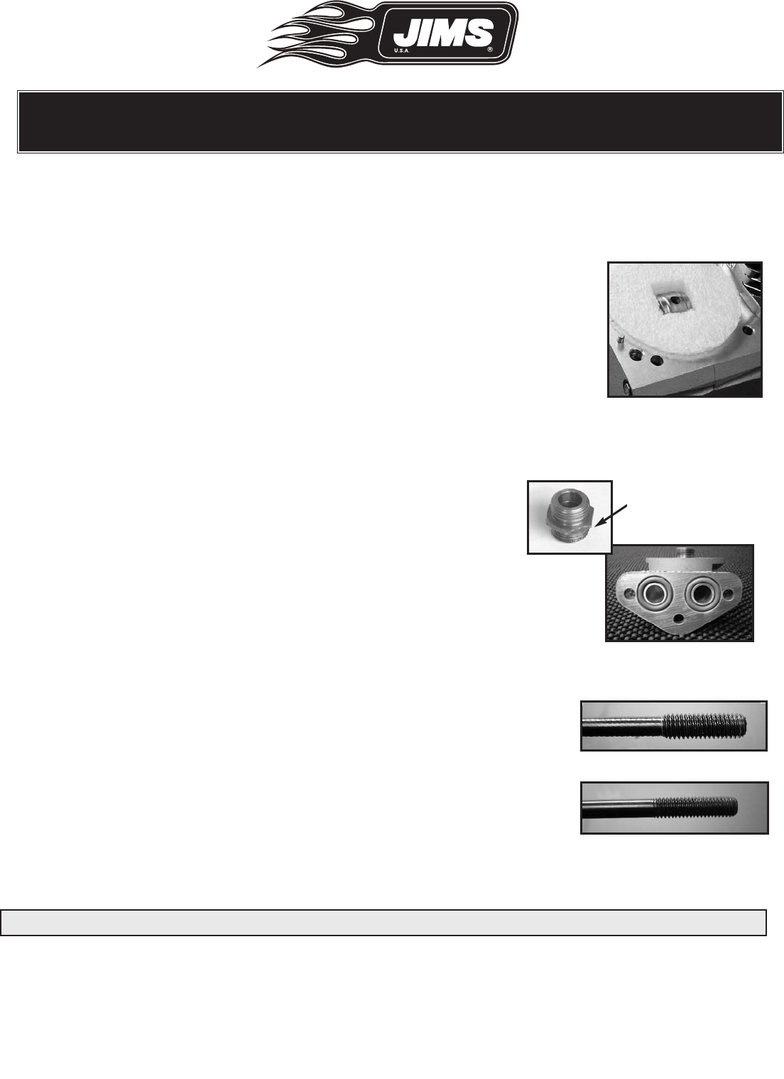
STEP 2: Inspect the oil filter o-ring sealing surface
• Sealing surface should be smooth and flat.
• If necessary clean thoroughly, set aside and cover. See Fig.8 for Engine “A”
• Inspect both threads for any burrs or dents on oil filter adapter No.1486-
1835.
STEP 3: Base Gasket Surface Preparation
• Clean base gasket surface (case deck) with a clean lint free cloth
and (denatured alcohol/isopropyl alcohol)
• Make certain the cylinder seating surfaces of the cases are
smooth, clean and dry. See Fig. 9.
• Confirm the eight stud holes in the cases are empty, clean and dry.
STEP 4: Stud Installation: See Fig.7 & Fig. 8.
Note: These studs are not designed to be an interference fit, however there
may be slight drag on some studs as they are installed into the case.
• Each stud is installed with two (2) small drops of Loctite 620 on the
first four (4) threads, and (2) small drops in each cylinder stud case
hole.
Fig.7- 3/8” Head bolt end
Fig.8- 7/16” Case stud end
Fig.6 - Oil filter unit
Oil Filter Adapter
for Engine “B”, and
“A” - 06-Pres FXD, &
07-Pres FL No.1486-
1835
Note: Dirt is an engine’s worst enemy!
Fig.5- Clean surfaces


