T6811DP08/T6812DP08 DIGITAL THERMOSTAT
62-0325ES—01 2
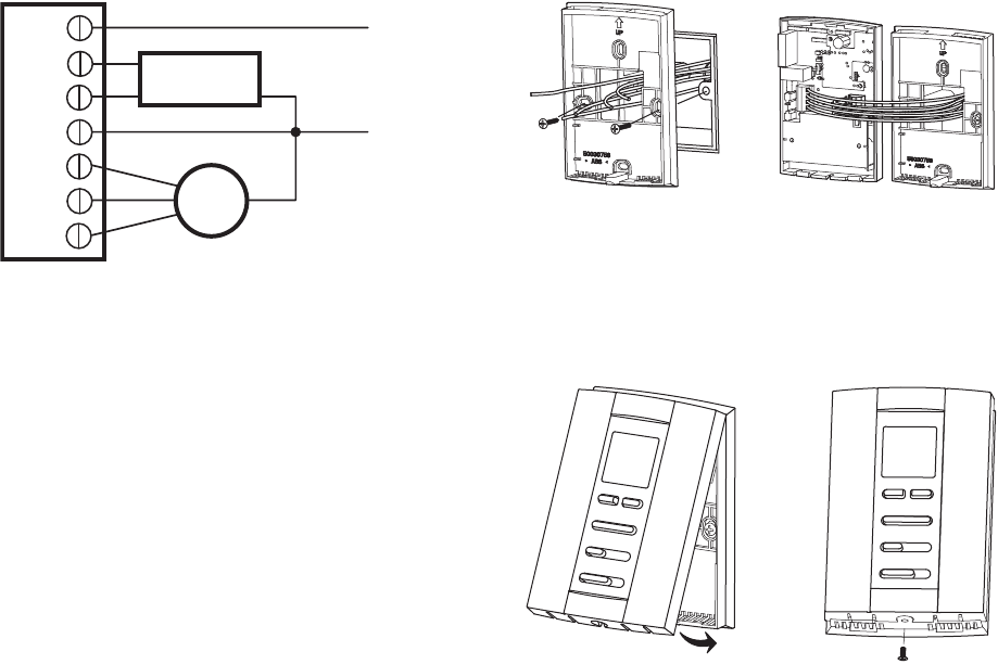
Fig. 2. Typical wiring for ON/OFF control in 2 pipes Heat/
Cool/1H1C (for 3-wire valve actuators).
Installation
1. Pull the wires through the wire hole on the wallplate and
place the back cover over the junction box.
2. Insert the mounting screws and tighten. See Fig. 3, left.
3. Loosen screw terminals used for the application. Insert
the wires into the terminal block and tighten each screw
terminal. See Fig. 3, right.
Fig. 3. Wiring thermostat.
4. Align the top of the thermostat with the back cover and
push down on the back cover. See Fig. 4, left.
5. Insert the locking screw into the whole on the bottom of
the thermostat and tighten. See Fig. 4, right.
Fig. 4. Installing thermostat.
FAN
VALVE
L
N
L
Ch/Cc
W/Y
N
GI
Gm
Gh
M29505
M29506
M29507


