–
3
–
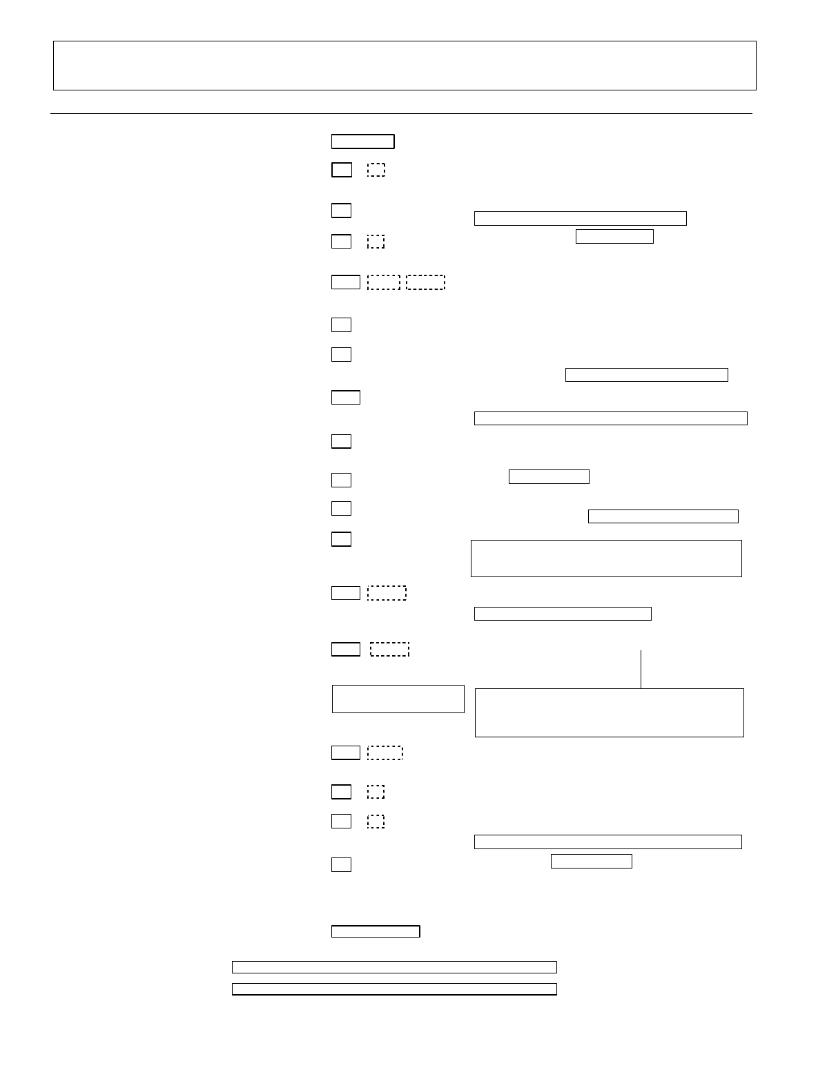
352*5$00,1*)250
Entries apply to both the FA168CPS and
FA148CP
controls, except
entries shown in dashed boxes, which apply only to the
FA168CPS (partition entries) and are not applicable to the FA148CP
.
Entry of a number other than one specified will give unpredictable results. Values shown in brackets are factory defaults.
Field Function Data Entries Programmable Values
SYSTEM SETUP (
✱
20–
✱
29)
✱
20
INSTALLER CODE
| | |
[4112]
4 digits, 0–9
✱
21
QUICK ARM ENABLE
[0,0]
Part. 1 Part.2
0 = no; 1 = yes
✱
22
RF JAM OPTION
[0]
0 = no RF Jam detection; 1 = send RF Jam report
UL: must be 1 if wireless devices are used
✱
23
QUICK (FORCED) BYPASS
[0,0]
Part. 1 Part. 2
0 = no quick bypass UL: must be “0”
1 = allow quick bypass (code + [6] + [#] )
✱
24
RF HOUSE ID CODE
| | |
Part. 1 Part. 2 Common
00 = disable all wireless keypad usage
01–31 = using 5827, 5827BD or 5804BD keypad
[00,00,00]
✱
26
CHIME BY ZONE
[0]
0 = no; 1 = yes (select zones to chime on zone list 3,
using *81 Menu mode)
✱
27
POWERLINE CARRIER DEVICE (X–10)
HOUSE CODE
[0]
0 = A; 1 = B, 2 = C, 3 = D, 4 = E, 5 = F, 6 = G,
7 = H, 8 = I, 9 = J, #10 = K, #11 = L, #12 = M, #13 = N,
#14 = O, #15 = P UL: not for fire or UL installations
✱
28
ACCESS CODE FOR
PHONE MODULE
| [00]
(Partition 1 only)
00 = disable; 1st digit: enter 1–9; 2nd digit: enter # + 11
for "
✱
", or # + 12 for "#".
UL: must be “00” for UL Commercial Burg. installations
✱
29
LONG RANGE RADIO OUTPUT
[0]
0 = disable; 1 = enable
ZONE SOUNDS AND TIMING (
✱
31 –
✱
39)
✱
31
SINGLE ALARM SOUNDING per ZONE
[0]
0 = no UL: must be “0”; 1 = yes
✱
32
FIRE ALARM SOUNDER TIMEOUT
[0]
0 = sounder stops at timeout;
1 = no sounder timeout UL: must be “1” for fire install.
✱
33
ALARM SOUNDER (BELL) TIMEOUT
[1]
0 = none; 1 = 4 min; 2 = 8 min; 3 =12 min; 4 = 16 min;
UL: For residential fire alarm installation, must be set for a
minimum of 4 min (option 1); for UL Commercial Burglary
installations, must be minimum 16 min (option 4)
✱
34
EXIT DELAY
| | [60,60]
Part. 1 Part. 2
00 - 96 = 0 - 96 secs; 97 = 120 secs
SIA Installations: minimum exit delay is 45 seconds
UL: see inst. instr. for requirements.
Common zones use same delay as partition 1.
✱
35
ENTRY DELAY #1 (zone type 01)
| | [30,30]
Part. 1 Part. 2
Common zones use same
delay as partition 1
.
00 - 96 = 0 - 96 seconds
97 = 120 seconds
SIA Installations:
98 = 180 seconds
minimum entry delay is
99 = 240 seconds
30 seconds
For UL Residential Burglary Alarm installations, must be set
for a maximum of 30 seconds; entry delay plus dial delay
should not exceed 1 min. For UL Commercial Burglar Alarm,
total entry delay may not exceed 45 seconds.
✱
36
ENTRY DELAY #2 (zone type 02)
| | [30,30]
Part. 1 Part. 2
See *35 Entry Delay 1 above for entries.
∗37
AUDIBLE EXIT WARNING
[1,1]
0 = no; 1 = yes
SIA Installations: must be enabled (enter 1)
✱
38
CONFIRMATION OF ARMING DING
[0,0]
Part. 1 Part. 2
0 = no; 1 = yes (wired keypads and RF)
2 = yes, RF only
UL: must be “1” for UL Commercial Burglar Alarm inst.
✱
39
POWER UP IN PREVIOUS STATE
[1]
0 = no; 1 = yes UL: must be “1”
DIALER PROGRAMMING (
✱
40 –
✱
42)
Do not fill unused spaces. Enter 0–9; #+11 for '
✱
'; #+12 for '#'; #+13 for a 2-second pause. If fewer than the maximum digits entered, exit the
field by pressing [
✶
]. The next data field number is displayed.
✱
40
PABX ACCESS CODE
| | | | |
Enter up to 6 digits. To clear entries, press
✱
40
✱
. If call waiting
used, enter “
∗
(#+11) 70” plus “# + 13” (pause).
✱
41
PRIMARY PHONE No.
| | | | | | | | | | | | | | | | | | |
✱
42
SECOND PHONE No.
| | | | | | | | | | | | | | | | | | |
Enter up to 20 digits. To clear entries, press
✱
41
✱
or
✱
42
✱
respectively
.


