MUTE
VOLUME
G
10K OHMS
2K OHMS
MAX
2 C
3
1 V
MIN
123
STANDBY
MUTE SWITCH
VOL/MUTE
10V 50 mA
45
or
REMOTE
G
GCV
10V 50mA
STANDBY
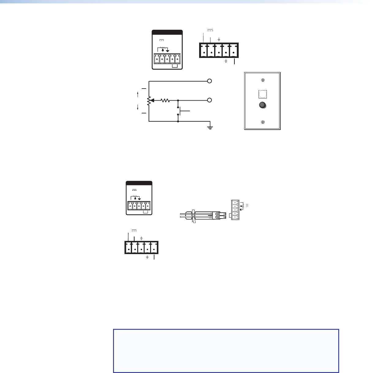
Pin 5 (standby) connected to ground (pin 4) places the amplifier in standby mode.
Standby mode turns off all output, although the amplifier is still receiving power.
Use the included 2-pin, 3.5 mm captive screw connector to remotely ground pin
5. The power indicator LED lights amber when the amplifier is in standby mode.
Remote Switching to Standby Mode
123 45
STANDBY
VOL/MUTE
10V 50 mA
STANDBY
G
V
GC
10V
50mA
or
REMOTE
G
GCV
10V 50mA
STANDBY
å
Stereo audio output connector — Marked “1” and “2” for the output channels,
wire the included 4-pole, 5 mm screw lock captive screw connector to output stereo
audio. Observe the correct polarities for each channel (see the following steps).The
output is designed to power 4 or 8 ohm speaker systems and is rated for 100 watts
per channel at 4 ohms and 60 watts per channel at 8 ohms for the non-Plus model,
and 100 watts per channel at 4 and 8 ohms for the Plus model.
NOTES:
• You must use Class 2 wiring for this output to comply with UL requirements.
• The stereo audio output connector may be labeled one of two ways
(see the images on the following page). The wiring and function are the
same, whichever way your product is labeled.
XTRA Series Half-Rack Audio Power Amplifiers • Operation
14


