EPL-N2700 Revision A
Appendix Connector Summary 139
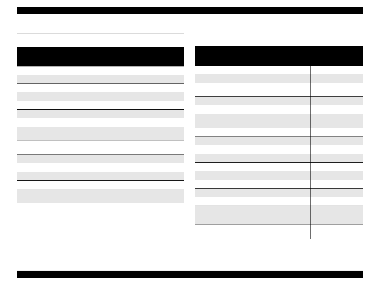
7.1 Connector Summary
Table 7-1. Connector Summary - C269MAIN Circuit Board (PWB-P)
Table 7-2. Connector Summary - Engine Controller Board (PWB-A)
Connector
number
Number of
pins
Constituent to which the
connector is connected
Constituent to which
the other end of the
harness is connected
CN1 36 IEEE-1284 parallel interface -
CN2 25 RS-232C serial interface -
CN3 26 Control panel -
CN4 32 Video interface PWB-A PJ1
CN5 20 Type-B interface -
CN7 50 (IDE hard disc) -
CN8 168 SDRAM DIMM -
CN9 -
SCSI (Not used. Reserved for
board development.)
-
CN10 -
CPU bus (Not used. Reserved
for board development.)
-
CN11 72 ROM DIMM0 A socket -
CN12 72 ROM DIMM1 B socket -
CN13 72 ROM DIMM2 C socket -
CN14 72 CODE DIMM PROG socket -
CN15, C16 -
Not used. Reserved for board
development.
-
Connector
number
Number of
pins
Constituent to which the
connector is connected
Constituent to which
the other end of the
harness is connected
PJ1 32 Video interface PWB-P CN4
PJ2 4 Low voltage power supply PU1 PJ5
PJ3 13
2nd cassette and option
cassette control
2nd cassette control
board PJ1
PJ4 20 Option interface Duplex unit
PJ5 9 Option interface 5-bin unit
PJ6 2
Power supply for the power
supply unit cooling fan
Power supply unit cooling
fan
PJ7 3 Right door interlock switch -
PJ8 5 Polygon motor control Printhead unit
PJ9 6 Video signal Printhead unit
PJ10 2 Low voltage power supply PU1 PJ5
PJ11 - Not used -
PJ12 7 Option interface 10-bin unit
PJ13 26 Sensors -
PJ14 28 Sensors High voltage uni, others
PJ15 - Not used -
PJ16 12
Motor control, Fuser unit
temperature control
Transport motor, I/C drive
motor, Fuser lamp
thermistor, PU1, PJ4
PJ17, PJ18,
PJ19, PJ21
- Not used -


