DCN Next Generation Automatic Camera Control en | 9
3.1.1 The menu bar
All menu options referred to in this user manual are
contained within the menu bar located under the title
bar at the top of the Camera Installation window.
The full list of menu options is as follows:
File Settings!... Configuration!
...
Camera List!... Help
Camera
Activity
Clear all
Print…
Import…
Export…
E
xit
Index…
Keyboard
Commands
Procedures
Glossary
Using Help
About…
3.2 Assigning cameras to seat/unit
numbers
i Note
Before you start the installation process make
sure that the configuration is correctly set.
To start the camera installation process:
• Click on the ‘Start’ button.
i Note
The ‘Start’ button toggles to a ‘Stop’ button
when activated. During camera installation, all
conference activities will be stopped.
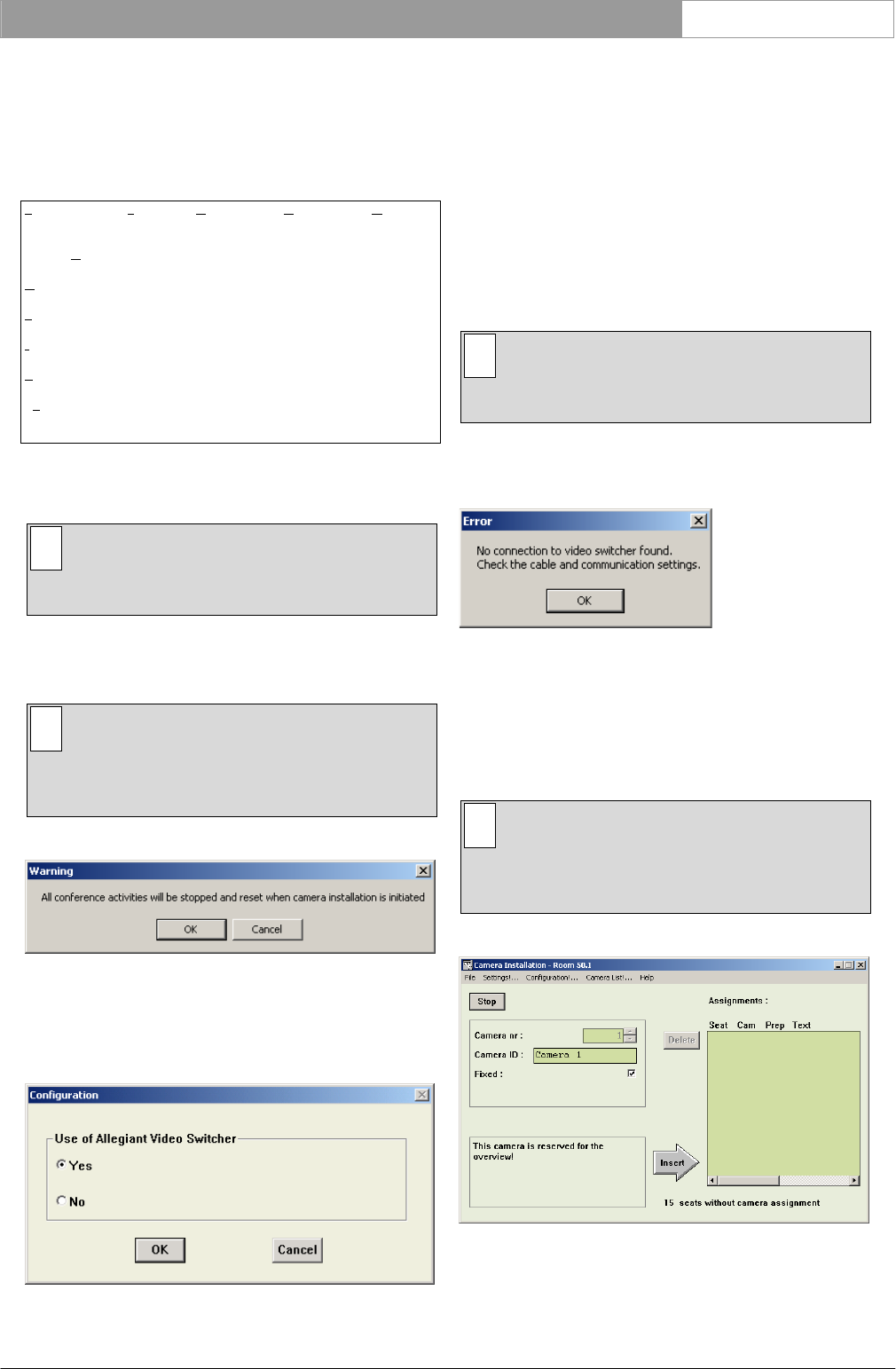
The following warning appears:
Figure 5 Camera installation warning
• Click on ‘OK’ to continue with camera
installation.
The following window appears:
Figure 6 Configuration window
In this window must be select if an Allegiant video
switcher is used or not.
If ‘Yes’ is chosen the Allegiant Video Switcher (AVS)
mode is selected. If ‘No’ is chosen the Direct Camera
Control (DCC) mode is selected.
In case of AVS several cameras are connected via a
Allegiant video switcher to the system and
screenlines can be added to the camera images.
In case of DCC the camera is directly connected to
the system and only images with the addition of
screen lines can be used.
i Note
If you want to change the control mode at any
other time go to Configuration!... in the menu.
If there is no communication between the CCU and
the Allegiant video switcher, the following error
message appears:
Figure 7 No connection to video switcher error
message
• Click on ‘OK’ and ensure that the connection,
cable and communication settings between the
Allegiant video switcher and the CCU are
correctly made.
i Note
In case of Direct Camera Control there is no
warning when there is no connection between
the AutoDome and the CCU.
The following window appears:
Figure 8 The Camera Installation window
Bosch Security Systems B.V. | 2005 January | 9922 141 70491
