Manual 2100-581B
Page 2 of 26
Contents
Figures
Figure 1 Fresh Air Damper Assembly .....................5
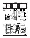
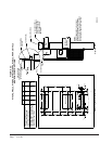
Figure 2 Unit Dimensions ....................................... 7
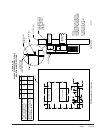
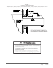
Figure 3A Mounting Instructions ............................... 8
Figure 3B Mounting Instructions - W17 – 36 ................9
Figure 3C
Mounting Instructions - W42, 48, 60, 70 ....10
Figure 4 Electric Heat Clearance ......................... 11
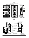
Figure 5 Wall Mounting Instructions .....................12
Figure 6 Wall Mounting Instructions .....................12
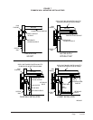
Figure 7 Common Wall Mounting Installations ..... 13
Figure 8 Fan Blade Setting ...................................18
Tables
Table 1 Fan Blade Dimensions ........................... 18
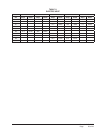
Table 2 Cooling Pressure ....................................19
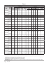
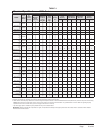
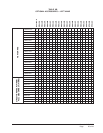
Table 3 Electrical Specications W**A ................ 20
Table 4 Electrical Specications W**L ................21
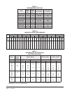
Table 5 Recommended Airow ...........................22
Table 6 Indoor Blower Performance ...................22
Table 7 Maximum ESP Electric Heat Only ..........22
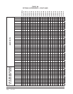
Table 8 Electric Heat ...........................................23
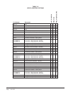
Table 9A Optional Accessories — Right Hand ...... 24
Table 9B Optional Accessories — Left Hand ............25
Table 10 Vent & Control Options ...........................26
Getting Other Information and Publications 3
Wall Mount General Information
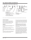
Wall Mount Model Nomenclature
..............................4
Shipping Damage
.....................................................4
General .................................................................4
Duct Work
.................................................................5
Filters .................................................................5
Fresh Air Intake
.........................................................5
Condensate Drain
.................................................... 5
Installation Instructions
Wall Mounting Information
........................................6
Mounting the Unit
......................................................6
Clearances Required
................................................6
Minimum Clearances
................................................6
Wiring – Main Power
...............................................14
Wiring – Low Voltage Wiring
................................... 14
Start Up
General ...............................................................15
Topping Off System Charge
....................................15
Safety Practices
...................................................... 15
Important Installer Note
...........................................16
High Pressure Switch
..............................................16
Three Phase Scroll Compressor
.............................16
Phase Monitor
.........................................................16
Condenser Fan Operation
......................................16
Service Hints
...........................................................16
Sequence of Operation
........................................... 17
Compressor Control Module
................................... 17
Adjustments
............................................................17
Pressure Service Ports
...........................................17
Troubleshooting
Fan Blade Setting Dimensions
................................18
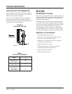
R-410A Refrigerant Charge
....................................18
Removal of Fan Shroud
.......................................... 18