Manual 2100-467D
Page 18 of 25
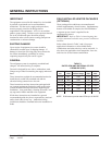
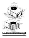
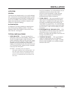
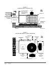
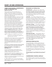
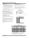
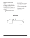
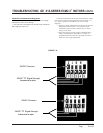
FAN BLADE SETTINGS
Shown in Figure 8 are the correct fan blade setting
dimensions for proper air delivery across the outdoor
coil.
Any service work requiring removal or adjustment in
the fan and/or motor area will require that the
dimensions below be checked and blade adjusted in or
out on the motor shaft accordingly.
"B"
MD-1417BC
SERVICE AND TROUBLESHOOTING
SERVICE HINTS
1. Caution homeowner to maintain clean air filters at
all times. Also, not to needlessly close off supply
and return air registers. This reduces airflow
through the system which shortens equipment
service life as well as increasing operating costs.
2. Check all power fuses or circuit breakers to be sure
that they are the correct rating.
3. Periodic cleaning of the outdoor coil to permit full
and unrestricted airflow circulation is essential.
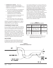
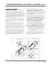
PRESSURE SERVICE PORTS
High and low pressure service ports are installed on all
units so that the system operating pressures can be
observed. Pressure tables can be found later in this
manual covering all models on cooling cycle. It is
imperative to match the correct pressure table to the
unit by model number.
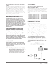
REFRIGERANT CHARGE
The correct system R-410A charge is shown on the unit
rating plate.
You can reference Tables 10 & 11 to validate proper
system performance. However, it is recommended that
if incorrect charge is suspected, the system be
reclaimed, evacuated and charged to the nameplate
quantity and type.
The nameplate charge quantity is optimized for thermal
performance and efficiency of this self-contained
package system.
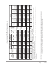
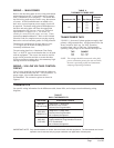
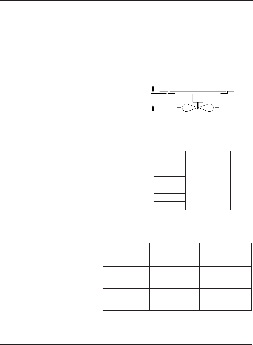
TABLE 8
FAN BLADE SETTING DIMENSIONS
ledoM"A"noisnemiD
4231AP
"¼3
0331AP
6331AP
2431AP
8431AP
0631AP
“A”
ledoM
detaR
PSE
XAM
PSE
2
suounitnoC
wolfriA
3
detaR
gnilooC
MFC
4
detaR
gnitaeH
MFC
4231AP01.005.0006008008
0331AP51.005.005700010001
6331AP51.005.052800110011
2431AP02.005.052900410041
8431AP02.005.0520105510551
0631AP02.005.0051105610561
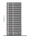
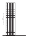
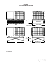
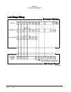
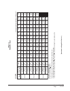
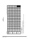
TABLE 9
INDOOR BLOWER PERFORMANCE
1
1 Motor will deliver consistent CFM through voltage supply range with no deterioration
(197-253V for all 230/208V models).
2 Continuous CFM is the total air being circulated during continuous (manual fan) mode.
3 Will occur automatically with a call for "Y" for cooling mode operation.
4 Will occur automatically with a call for "W1" for heating mode operation.
FIGURE 8
FAN BLADE SETTING