


363657-YTG-C-0708
Johnson Controls Unitary Products 3
HORIZONTAL SIDEWALL VENTING
For applications where vertical venting is not possible, the
only approved method of horizontal venting is the use of an
auxiliary power vent. Auxilary power venters must be
approved by CSA, UL, or other recognized safety agencies.
Follow all application and installation details provided by the
manufacturer of the power vent.
FILTER PERFORMANCE
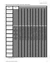
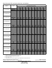
The airflow capacity data published in the “Blower Perfor-
mance” table listed above represents blower performance
WITHOUT filters.
All applications of these furnaces require the use of field
installed air filters. All filter media and mounting hardware or
provisions must be field installed external to the furnace cabi-
net. DO NOT attempt to install any filters inside the furnace.
NOTE: Single side return above 1800 CFM is approved as
long as the filter velocity does not exceed filter manufac-
turer’s recommendation and a transition is used to allow use
on a 20x25 filter.
NOTES:
1. Air velocity through throwaway type filters may not exceed 300
feet per minute (91.4 m/min). All velocities over this require the
use of high velocity filters.
2. Do not exceed 1800 CFM using a single side return and a 16x25
filter. For CFM greater than 1800, you may use two side returns or
one side and the bottom or one return with a transition to allow
use of a 20x25 filter.
Recommended Filter Sizes
CFM
Cabinet
Size
Side
(in)
Bottom
(in)
800 A 16 x 25 14 x 25
1000 A 16 x 25 14 x 25
1200 A 16 x 25 14 x 25
1200 B 16 x 25 16 x 25
1600 B 16 x 25 16 x 25
1600 C 16 x 25 20 x 25
2000 C (2) 16 x 25 20 x 25
2200 C (2) 16 x 25 20 x 25
2000 D (2) 16 x 25 22 x 25
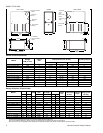
Unit Clearances to Combustibles (All dimensions in inches, and all surfaces identified with the unit in an upflow
configuration)
Application Top Front Rear
Left
Side
Right
Side
Flue
Floor/
Bottom
Closet Alcove Attic
Line
Contact
Upflow 1 6 0 0 3 6 Combustible Yes Yes Yes No
Upflow B-Vent 1 3 0 0 0 1 Combustible Yes Yes Yes No
Downflow 1 6 0 0 3 6
1
1
1. Special floor base or air conditioning coil required for use on combustible floor.
Yes Yes Yes No
Downflow B-Vent 1 3 0 0 0 1
1
1
Yes Yes Yes No
Horizontal 1 6 0 0 3 6 Combustible No Yes Yes
Yes
2
2. Line contact only permitted between lines formed by the intersection of the rear panel and side panel (top in horizontal position) of the furnace jacket and build-
ing joists, studs or framing.
Horizontal B-Vent 1 3 0 0 0 1 Combustible No Yes Yes
Yes
2