


036-21004-002 Rev. B (0602)
2 Unitary Products Group
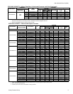
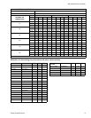
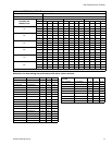
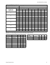
Physical and Electrical Data
MODEL
FRCS0241BD FRCS0301BD FRCS0361CD FRCS0421CE FRCS0481CE FRCS0601BF
Unit Supply Voltage 208 / 230 - 1 – 60
Normal Voltage Range
1
187 to 252
Minimum Circuit Ampacity 12.1 14.9 18.1 17.8 20.6 31.8
Max Overcurrent Device Amps
2
20 20 25 30 35 50
Compressor Type
3
Inertia Inertia
Scroll
C
Scroll
C
Scroll
C
Scroll
B
Compressor Amps
Rated Load 9.3 10.9 13.5 13.2 15.5 24.3
Locked Rotor 57 64 73 95 109 150
Crankcase Heater No No No No No No
Fan Motor Amps Rated Load .5 1.3 1.3 1.3 1.3 1.4
Fan Diameter Inches 22 22 22 24 24 24
Fan Motor
Rated HP 1/15 1/4 1/4 1/4 1/4 1/3
Nominal RPM 830 825 825 825 825 1100
Nominal CFM 2,260 3,300 3,300 3,300 3,300 3,500
Coil
Face Area Sq Ft 19.65 23.58 23.58 22.5 27.0 27.0
Rows Deep 1 1 1 2 2 2
Fin /Inch 18 18 18 18 18 18
Liquid Line OD 3/8 3/8 3/8 3/8 3/8 3/8
Vapor Line OD 7/8 7/8 7/8 1 1/8 1 1/8 1 1/8
Unit Charge (Lbs - Oz)
4
8 - 0 9 - 14 9 - 6 14 - 0 14 - 3 15 - 13
Charge Per Foot, oz. 0.70 0.70 0.70 0.76 0.76 0.76
Operating Weight Lbs 209 228 219 240 264 270
1. Rated in accordance with ARI Standard 110, utilization range “A”.
2. Dual element fuses or HACR circuit breaker.
3. All scrolls listed with superscript “B” are Bristol scrolls. All scrolls listed with superscripts “C” are Copeland scrolls.
4. The Unit Charge is correct for the outdoor unit, matched indoor coil and 15 feet of refrigerant tubing. For tubing lengths other than 15
feet, add or subtract the amount of refrigerant, using the difference in length multiplied by the per foot value.
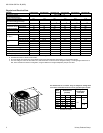
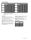
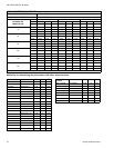
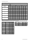
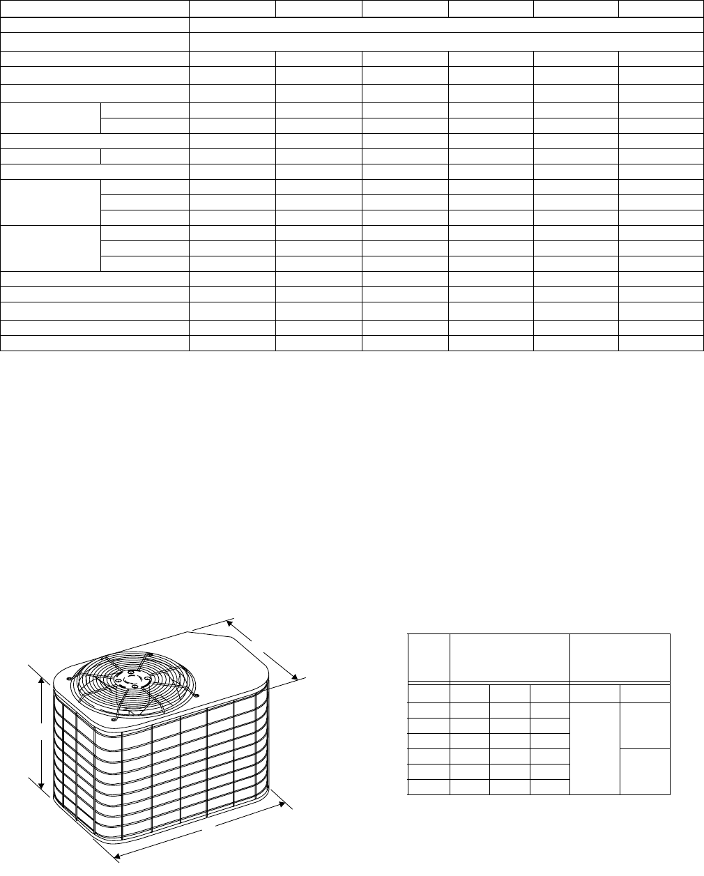
A
B
C
All dimensions are in inches. They are subject to change wit
h
out notice. Certified dimensions will be provided upon request
.
Unit
Model
Dimensions
(Inches)
Refrigerant
Connection
Line Size
A
1
1. Included Fan Guard
B C Liquid Vapor
024 33 37 27
3/8
7/8030 39 37 27
036 39 37 27
042 32 43 32
1-1/8048 38 43 32
060 38 43 32