


271015-UUM-A-0407
Unitary Products Group 3
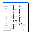
HOW YOUR GAS FURNACE WORKS
Your furnace is a very easy appliance to take for granted. Season after
season, it sits there in your home, keeping you warm and comfortable.
For this reason, you may never have given much thought to the way
your furnace operates. In order to get the safest and most efficient oper-
ation from your furnace, you should understand how your furnace does
its job.
When you set your thermostat to provide more heat in your home, you
are starting the heating cycle of the furnace. First, the inducer motor
starts to purge the heat exchanger of any remaining gases. Next, the
hot surface ignitor glows and after a warm-up period the gas valve
opens and ignition occurs. A short time later, the blower starts and dis-
tributes the warm air throughout the home. When the temperature set-
ting on your thermostat is reached, the gas valve closes, the main
burners are turned off, and the blower continues to run until the remain-
ing warm air in the system is distributed. When the blower stops, the
heating cycle has ended.
START-UP AND SHUTDOWN INSTRUCTIONS
Read the Instructions Below Before Trying to Start the
Furnace
A. This appliance does not have a pilot. It is equipped with an ignition
device which automatically lights the burner. Do not try to light the
burner by hand.
B. BEFORE OPERATING; smell all around the appliance area for
gas. Be sure to smell next to the floor because some gas is
heavier than air and will settle on the floor.
C. Use only your hand to push the gas control switch to the “on” posi-
tion. Never use tools. If the switch will not operate by hand, don’t
try to repair it, call a qualified service technician. Force or
attempted repair may result in a fire or explosion.
D. Do not use this appliance if any part has been under water. Imme-
diately call a qualified service technician to inspect the appliance
and to replace any part of the control system and any gas control,
which has been under water.
Operating Instructions:
1. STOP! Read the safety information above.
2. Set the thermostat to the lowest setting.
3. Turn off all electric power to the appliance.
4. Remove burner access panel.
5. Move gas control switch to the “OFF” position. Do not force. See
Figure 4.
6. Wait five (5) minutes to clear out any gas. If you then smell gas,
STOP! Follow “B” in the safety information above. If you don’t
smell gas, go to next step.
7. Move gas control switch to the “ON” position. Do not force. See
Figure 4.
8. Replace burner access panel.
9. Turn on all electric power to the appliance.
10. Set thermostat to the desired setting. Burner will light, which may
take 30-60 seconds.
11. After three (3) trials for ignition, if the appliance will not operate fol-
low the instructions, “TO TURN OFF THE APPLIANCE” and call
your service technician or gas supplier.
To Turn Off the Appliance:
1. Set the thermostat to lowest setting.
2. Turn off all electric power to the appliance if service is to be per-
formed.
3. Remove burner access panel.
4. Move gas control switch to the “OFF” position. See Figure 4.
5. Replace burner access panel.
NOTE: The spring-loaded safety cut-off switch, mounted under the
blower deck will automatically cut off the electrical power supply to the
furnace when the blower panel is removed. As a safety precaution, all
electrical power and the gas supply to the furnace should be turned off
before servicing.
FURNACE USER MAINTENANCE
If you do not follow these instructions exactly, a fire or
explosion may result causing property damage, personal
injury, and/or loss of life.
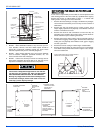
Should overheating occur, or the gas valve fail to shut off,
turn the external manual gas valve in the gas supply line to
the furnace to the “off” position and let the furnace cool off
before shutting off the electrical power supply. Refer to
Figure 5.
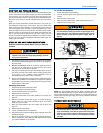
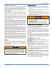
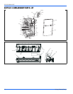
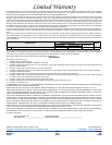
FIGURE 4: Gas Valve
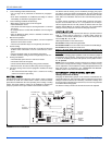
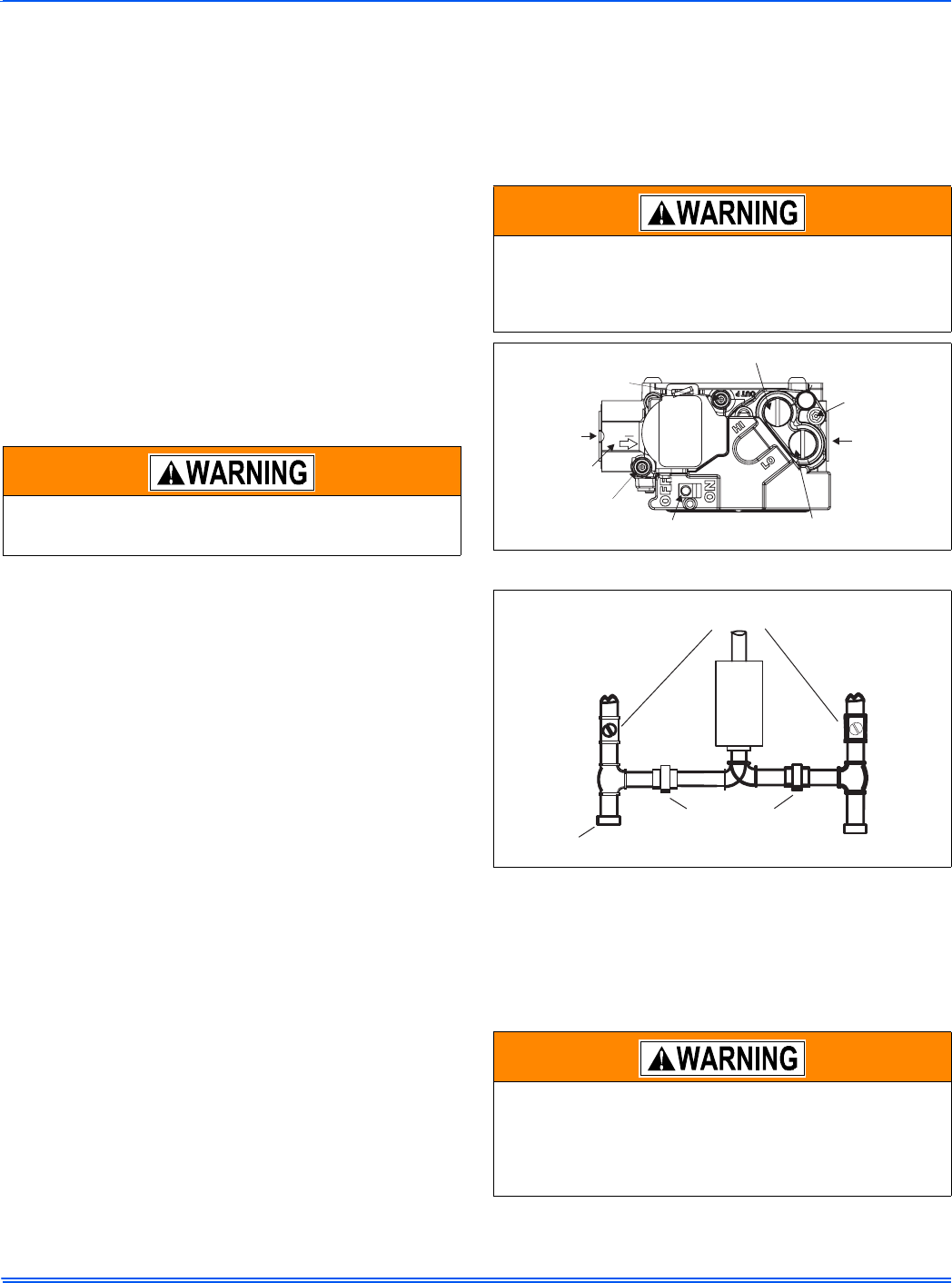
FIGURE 5: Gas Piping
Before proceeding, be sure the area is well ventilated. Turn
the thermostat OFF. If the blower is running, wait until it
stops automatically. Turn OFF the gas and electrical power
supplies to the furnace. Check all metal parts and surfaces
to be sure they have cooled to room temperature before
you begin.
INLET
WRENCH
BOSS
INLET
PRESSURE
PORT
ONOFF
SWITCH
LOWSTAGEREGULATOR
ADJUSTMENT
OUTLET
OUTLET
PRESSURE
PORT
VENT
PORT
HIGHSTAGEREGULATOR
ADJUSTMENT
EXTERNAL MANUAL
SHUTOFF VALVE
TO GAS
SUPPLY
TO GAS
SUPPLY
GROUNDED JOINT UNION
MAY BE INSTALLED
INSIDE OR OUTSIDE UNIT.
DRIP
LEG