


127408-YIM-B-0606
Unitary Products Group 21
OPTIONAL ELECTRIC HEAT
The factory-installed heaters are wired for single point power
supply. Power supply need only be brought into the single
point terminal block.
These CSA approved heaters are located within the central
compartment of the unit with the heater elements extending
into the supply air chamber.
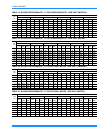
Fuses are supplied, where required, by the factory. Some kW
sizes require fuses and other do not. Refer to Table 14 for
minimum CFM limitations and to Tables 10 through 12 for
electrical data.
OPTIONAL GAS HEAT
These gas-fired heaters have aluminized-steel or optional
stainless steel, tubular heat exchangers with spark ignition.
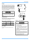
GAS PIPING
Proper sizing of gas piping depends on the cubic feet per
hour of gas flow required, specific gravity of the gas and the
length of run. "National Fuel Gas Code" Z223.1 should be
followed in all cases unless superseded by local codes or gas
utility requirements. Refer to the Pipe Sizing Table 16. The
heating value of the gas may differ with locality. The value
should be checked with the local gas utility.
NOTE: There may be a local gas utility requirement specify-
ing a minimum diameter for gas piping. All units
require a one-inch pipe connection at the entrance
fitting.
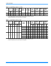
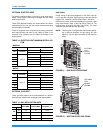
TABLE 14: ELECTRIC HEAT MINIMUM SUPPLY AIR
CFM
IMPERIAL
HEATER UNIT MODEL SIZE, NOMINAL TONS
kW
VOLTAGE
10 12.5
MINIMUM SUPPLY AIR CFM
9
380/415
N/A N/A
18
3000 3750
24
3000 3750
36
3000 3750
54
3000 3750
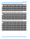
METRIC
HEATER UNIT MODEL SIZE, NOMINAL TONS
kW
VOLTAGE
10 12.5
MINIMUM SUPPLY AIR CFM
9
380/415
N/A N/A
18
1.41 1.76
24
1.41 1.76
36
1.41 1.76
54
1.41 1.76
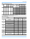
TABLE 15: GAS APPLICATION DATA
Unit
Input (MBH) Output (MBH) Temp Rise (°F)
Size Opt.
090
10 120 96 15-45
15 175 140 30-60
120 15 175 140 15-45
150 15 175 140 10-40
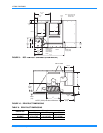
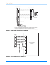
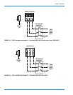
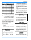
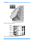
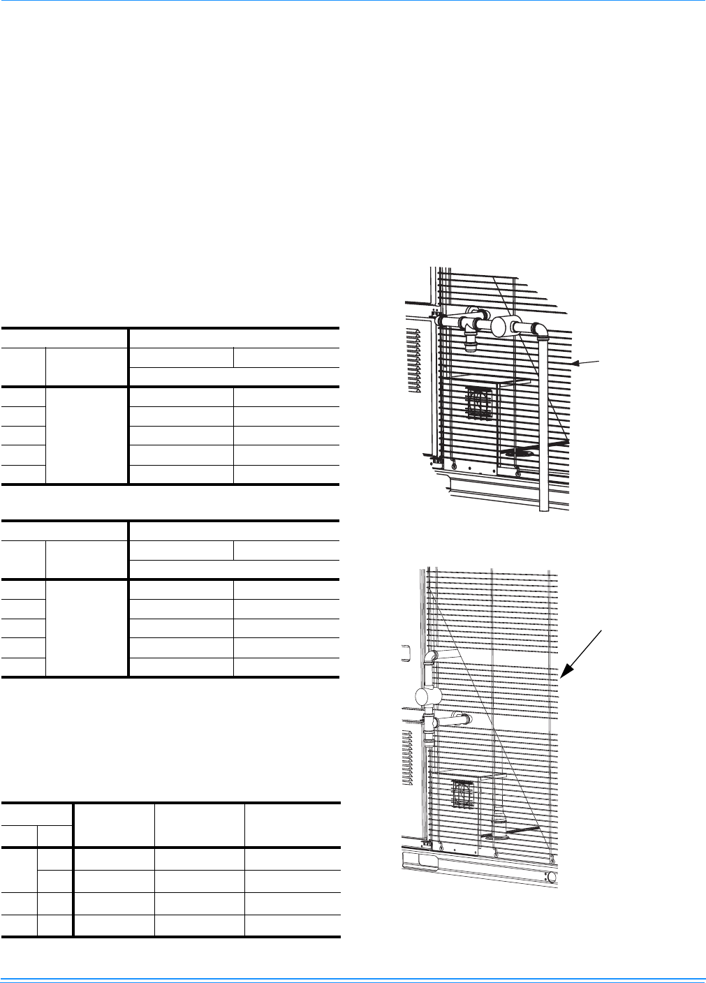
FIGURE 21 - SIDE ENTRY GAS PIPING
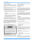
FIGURE 22 - BOTTOM ENTRY GAS PIPING
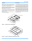
O P T I O N A L
C O I L
G U A R D
S H O W N
OPTIONAL
COIL
GUARD
SHOWN