


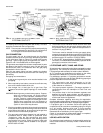
DUCT COVERS - Units are shipped with all air duct
openings covered.
For
side duct applications;
1. Remove and discard the supply and return air duct
covers.
2. Connect ductwork to duct flanges on the rear of the
unit.
For
bottom duct applications;
1. Remove the side supply air duct cover to gain
access to the bottom supply air knockout panel.
2. Remove and discard the bottom knockout panel.
3. Replace the side duct cover.
4. With filter section access panel removed from the
unit, remove and discard the bottom return air
knockout panel.
5. Replace the filter access panel.
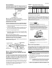
SCROLL COMPR.
ACCESS
11
1
⁄
2
4
5
⁄
8
3
7
7
⁄
8
6
1
⁄
2
17
1
⁄
2
11
1
⁄
2
17
1
⁄
2
REAR VIEW
SIDE SUPPLY AND RETURN
Front 32"
Back
12" (Less Economizer)
36" (With Economizer or Fixed
Air/Motorized Air Damper)
Left Side (Filter Access)
24" (Less Economizer)
36" (With Economizer)
Right Side (Cond. Coil) 24"
Below Unit
1
20"
Above Unit
2
72" (For Condenser Air Discharge)
1
Units may be installed on combustible floors made from wood or class A, B or C
roof covering material (Applicable in the U.S.A. only).
2
Units must be installed outdoors. Overhanging structures or shrubs should not
obstruct the outdoor coil nor the fan outlet.
NOTE: A 1" clearance must be provided between any combustible material and the
supply air ductwork for a distance of 3 feet from the unit.
The products of combustion must not be allowed to accumulate within a confined
space and recirculate.
Locate unit so that the vent air outlet hood is at least:
•
Three (3) feet above any forced air inlet located within 10 horizontal feet
(excluding those integral to the unit).
•
Four (4) feet below, 4 horizontal feet from, or 1 foot above any door or gravity air
inlet into the building.
•
Four (4) feet from electric meters, gas meters, regulators and relief equipment.
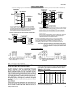
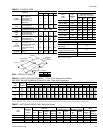
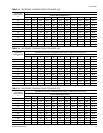
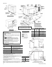
CLEARANCES
All dimensions are in inches. They are sub-
ject to change without notice. Certified di-
mensions will be provided upon request.
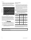
AIR FLOW LEGEND
RETURN AIR
SUPPLY AIR
OUTDOOR AIR
OUTDOOR AIR
(Economizer)
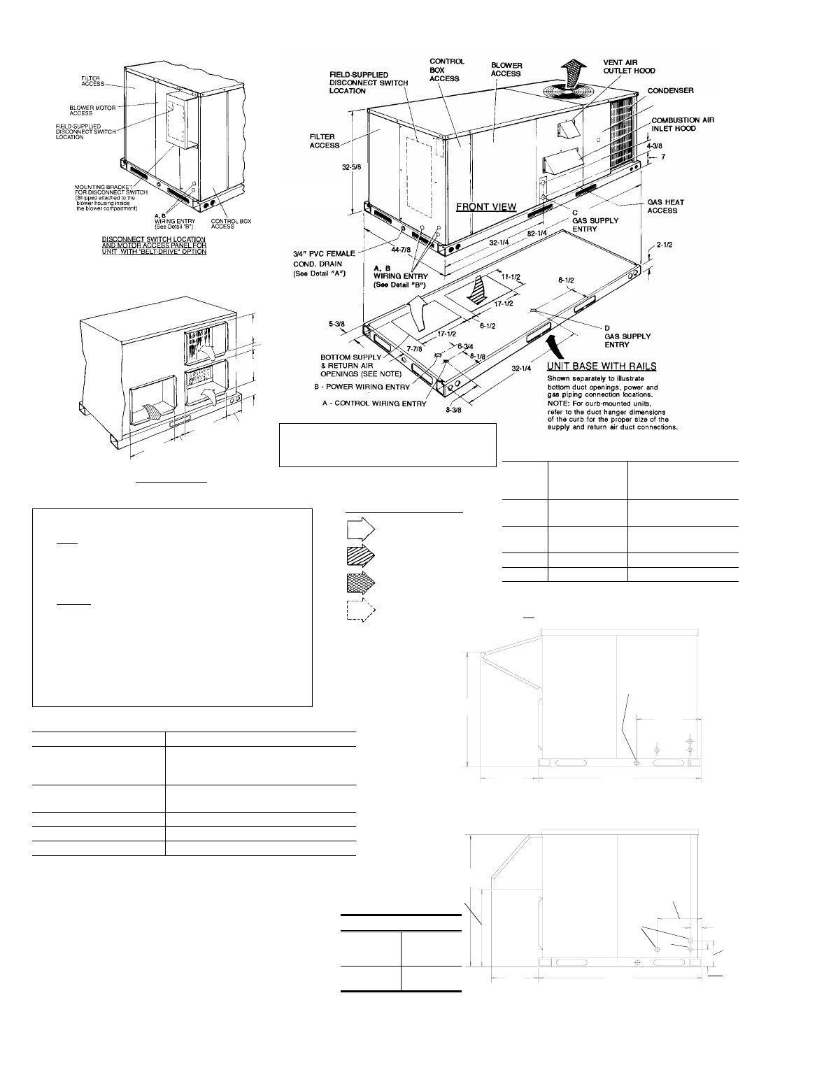
HOLE
KNOCKOUT
SIZE
(DIA.)
USED FOR
A7/8" *
Control Wiring
(Side or Bottom)**
B2" *
Power Wiring
(Side or Bottom)
C 1-5/8" Gas Piping (Front)
D 1-1/2" Gas Piping (Bottom)
*
Knockouts in the bottom of the unit can be located by the slice
in the insulation.
**
Do not remove the 2" knockout ring.
UTILITIES ENTRY DATA
FIG. 9 -
DIMENSIONS AND CLEARANCE (3, 4, 5 & 6 TON)
(Direct-Drive Units)
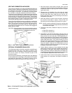
UNIT WITH ECONOMIZER RAIN HOOD
44
7
⁄
8
B
30
7
⁄
8
"A"
10
1
⁄
4
4
3
⁄
8
A
3
1
⁄
2
8
1
⁄
4
19
1
⁄
8
44
7
⁄
8
19
1
⁄
2
27
1
⁄
2
19
3
⁄
4
3
⁄
4
“ CONDENSATE
DRAIN
(must be trapped)
DETAIL “A”
DETAIL “B”
DIMENSION "A"
FIXED
OUTDOOR
AIR DAMPER
12
MOTORIZED
DAMPER
16
1
⁄
2
UNIT WITH FIXED OUTDOOR
AIR/MOTORIZED DAMPER RAIN HOOD
530.18-N8Y
14 Unitary Products Group