


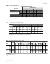


HEAT ANTICIPATOR SETPOINTS
It is important that the anticipator setpoint be correct. Too high
of a setting will result in longer heat cycles and a greater
temperature swing in the conditioned space. Reducing the
value below the correct setpoint will give shorter “ON” cycles
and may result in the lowering of the temperture within the
conditioned space. Refer to the Heat Anticipator Setting Table
for the required heat anticipator setting.
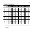
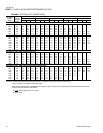
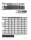
CHECKING SUPPLY AIR CFM
The RPM of the supply air blower will depend on the required
CFM, the unit options/accessories and the static resistances of
both the supply and the return air duct systems. With this
information, the RPM for the supply air blower and the motor
pulley adjustment (turns open) can be determined from the
Blower Performance Data Tables.
High speed drive accessories (containing a smaller blower
pulley and a shorter belt) are available for applications requiring
the supply air blower to produce higher CFM’s and/or higher
static pressures. Use Model 1LD0416 for 15 ton units and
Model 1LD0417 for 20 ton units. Refer to the Blower Motor and
Drive Data table.
Note the following:
1. The supply air CFM must be within the limitations shown in
Unit Application Data table.
2. Pulleys can be adjusted in half turn increments.
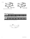
3. The tension on the belt should be adjusted as shown in the
Belt Adjustment Figure.
Start the supply air blower motor. Adjust the resistances in both
the supply and the return air duct systems to balance the air
distribution throughout the conditioned space. The job
specifications may require that this balancing be done by
someone other than the equipment installer.
To check the supply air CFM after the initial balancing has been
completed:
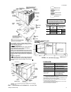
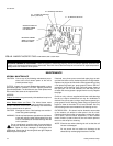
1. Remove the two 5/16" dot plugs from the blower motor and
the filter access panels shown in the Dimensions and
Clearances Figure.
2. Insert at least 8" of 1/4 inch tubing into each of these holes
for sufficient penetration into the air flow on both sides of
the indoor coil.
NOTE: The tubes must be inserted and held in a position
perpendicular to the air flow so that velocity pres-
sure will not affect the static pressure readings.
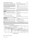
3. Using an inclined manometer, determine the pressure drop
across a dry indoor coil. Since the moisture on an indoor
coil may vary greatly, measuring the pressure drop across
a wet coil under field conditions would be inaccurate. To
assure a dry coil, the compressors whould be de-activated
while the test is being run.
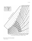
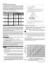
4. Knowing the pressure drop across a dry coil, the actual
CFM through the unit and clean 2" filters, can be
determined from the curve in the figure below.
WARNING: Failure to properly adjust the total system air
quantity can result in extensive blower damage.
After readings have been obtained, remove the tubes and
reinstall the two 5/16" dot plugs that were removed in Step 1.
NOTE: DE-ENERGIZE THE COMPRESSORS BEFORE TAKING
ANY TEST MEASUREMENTS TO ASSURE A DRY INDOOR
COIL.
BELT DRIVE BLOWER
All units have belt drive single-speed blower motors. The
variable pitch pulley on the blower motor can be adjusted to
obtain the desired supply air CFM.
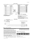
FIG.9 -
BELT ADJUSTMENT
HEATER
KW
VOLTAGE
SETTING, AMPS
TH1 TH2
18
208/230-3-60
0.29 -
36 0.29 0.29
54 0.29 0.58
72 0.58 0.58
18
460-3-60
0.29 -
36 0.29 0.29
54 0.29 0.29
72 0.29 0.29
18
575-3-60
0.29 -
36 0.29 0.29
54 0.29 0.29
72 0.29 0.29
TABLE 13
- HE AT A NTICI PATO R SETT ING
FIG. 10 -
PRESSURE DROP ACROSS A DRY INDOOR
COIL VS SUPPLY AIR CFM
511.06-N3Y
16 Unitary Products Group