


66441-YUM-D-1011
Johnson Controls Unitary Products 5
CLEANING BURNERS
Remove them from the furnace as explained in BURNER
INSTRUCTIONS section in the Unit Installation Instructions.
Clean burners with wire brush and vacuum as needed.
CLEANING FLUE PASSAGES AND
HEATING ELEMENTS
With proper combustion adjustment, the heating element of a
gas fired furnace will seldom need cleaning. If the element
should become sooted, it can be cleaned as follows:
1. Remove the burner assembly as outlined in “BURNER
INSTRUCTIONS” of the unit installation instructions.
2. Remove the unit roof from over the gas heat section.
3. Remove the top plate and the top draft blower wheel from
the upper draft blower housing.
4. Remove the screws holding the top of the flue collector
box. Carefully remove the top of the flue collector box with-
out ripping the adjacent insulation. Then remove the center
divider plate separating the upper and lower flue boxes.
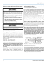
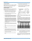
5. On the inside of the flue collector box, remove the flue baf-
fles from the tube interiors. Note the last bend of the baffle
fits tightly against the tube forcing the end of the baffle to
lock into the tube collar. This collar is formed when the tube
is expanded into the end sheet. To remove, move the end
of the baffle toward the center of the tube releasing the end
of the baffle from the tube collar, then pull straight out of the
tube. Refer to Figure 4.
6. Using a wire brush on a flexible wand, brush out the inside
of each heat exchanger from the burner inlet and flue outlet
ends.
7. Brush out the inside of the flue collector box and the flue
baffles.
8. Run the wire brush down the vent hoods from the flue col-
lector end.
9. If soot build-up is particularly bad, remove the vent motor
and clean the wheel and housings. Run the wire brush
down the flue extensions at the outlet of the vent housings.
10. After brushing is complete, blow all brushed areas with air
or nitrogen. Vacuum as needed.
11. Replace parts in the order they were removed in Steps 1
thru 5.
12. When replacing the center and top of the flue collector box,
be careful not to tear the adjoining insulation.
13. Ensure that all seams on the vent side of the combustion
system are air tight. Apply a high temperature (+500°F)
sealing compound where needed.
AIR FILTERS
All units contain 2" filters. Filters can be installed in the build-
ing at a suitable return air location if an economizer or outside
air accessory is not used. Filters must always be used. They
should be inspected once a month and thoroughly cleaned or
replaced if it appears they are beginning to accumulate
excessive dirt. Filter sizes and quantities are shown in the fol-
lowing table.
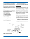
To install the filters, remove the filter access panel located to
the left of the condensate drain connection as shown in Fig-
ure 5.
NOTE: Filters must be installed with “Air Flow” arrows point-
ing inward -- toward the indoor coil. In the event the
spacers in the filter section are removed, they must
be reinstalled in their original position.
Slide filters all the way into the filter racks provided. When
more than one filter in a filter rack is required, they must butt
each other when sliding into position. Replace the filter
access panel.
FIGURE 4 - TYPICAL FLUE BAFFLE INSTALLATION
THROWAWAY
FILTER
SIZES
(Inches)
QUANTITY PER UNIT (Nom, Tons)
15 TON
STD
& HIGH
EFF.
15, 20, 25
TON REHEAT
20 TON
STD & HIGH
EFF.
25 TON
STD
EFF.
15 - 25
TON
ULTRA
HIGH
EFF.
12 x 24 - - 12 12
16x 20 - 4 - -
16 x 25 - 4 - -
18 x 24 5 - - -