


66386-YUM-C-1011
4 Johnson Controls Unitary Products
EXPLAIN UNIT FUNCTION
When the system is functioning properly, show the owner the
location of all disconnect switches and the thermostat.
Explain how to start and stop the unit and how to adjust tem-
perature settings within the limitations of the system. Advise
that the flue exhaust hood surface and the immediate area
will experience high temperatures during the heating cycle,
and that all unauthorized personnel and debris must be kept
away from this area.
GENERAL MAINTENANCE
In order to insure long and trouble free service from your sys-
tem, we recommend periodic inspection, cleaning, lubrication
and adjustment by your installing Dealer/Contractor. Be sure
to ask about this service. For those who prefer to do-it-your-
self, please follow the instructions listed below to care for
your system.
Snow or debris should not be allowed to accumulate in or
around the unit. Do not permit overhanging structures or
shrubs to obstruct outdoor air discharge, combustion air
inlets or vent outlets on your unit. These provide air for com-
bustion and ventilation. Adequate air is important to the safe
and proper operation of the unit.
HEATING SYSTEM INSPECTION
It is the owner's responsibility to insure that an annual inspec-
tion of the entire heating portion of the unit is made by a qual-
ified service technician. This should include inspection of the
burner, heating element and flue for any corrosion or soot
accumulation which may require cleaning and also checking
of burner and controls for proper operation.
In addition, at least once during the heating season, the
owner shall make a visual inspection of the flue outlet for evi-
dence of black soot or blockage of flue outlet by leaves or
other debris. If any soot is found, it is recommended a quali-
fied service technician be called immediately. If any blockage
is found, it must be cleared immediately.
Check for obvious signs of deterioration of the unit. Check
that the return and supply ducts attached to the unit are
sound and air tight. Check that the unit's physical support,
concrete slab or roof curb, is sound and not in need of repair.
Make sure there are no gaps between the roof curb and the
unit where rain could leak into the building.
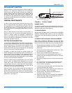
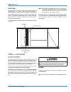
Start the furnace. The vent motor should start, the igniter will
start to spark and ignite the burner. If it does not, contact a
qualified service technician for assistance. Check the appear-
ance of the main burner flame. The flame should have a blue
appearance. (See Figure 3.)
BURNER CHECK
Periodically (at least annually at the beginning of each heat-
ing season) make a visual check of the main burner flame to
determine if the burners need cleaning.
CLEANING BURNERS
Remove them from the furnace as explained the in BURNER/
ORIFICE INSTRUCTIONS section in the Unit Installation
Instructions. Clean burners with wire brush and vacuum as
needed.
CLEANING FLUE PASSAGES & HEATING ELEMENTS
With proper combustion adjustment, the heat exchanger
tubes of a gas-fired furnace will seldom need cleaning. If the
tubes should become sooted, they can be cleaned as follows:
1. Remove the burner assembly as outlined in “BURNER/
ORIFICES INSTRUCTIONS” of the unit Installation
Instructions.
2. Remove the screws holding the flue collector box. Care-
fully remove the flue collector box.
3. Remove the flue baffles from the tube interiors.
4. Using a wire brush on a flexible wand, brush out the
inside of each heat exchanger from the burner inlet and
flue outlet ends.
5. Brush out the inside of the flue collector box and the flue
baffles.
6. Run the wire brush into the flue exhaust tube from the
flue collector end. Do not damage the flue exhaust
screen, remove if necessary.
7. If soot build-up is particularly bad, remove the draft motor
and clean the wheel and housing.
8. After brushing is complete, blow away all brushed areas
with air or nitrogen. Vacuum as needed.
9. Replace parts in the reverse order that they were
removed in Steps 1 through 3.
10. Assure that all seams on the vent side of the combustion
system are airtight. Apply a high temperature (500°F+)
sealing compound where needed.
FIGURE 3- TYPICAL FLAME
H E A T E X C H A N G E R T U B E
G A S
S U P P L Y
P I P E
B U R N E R
B U R N E R B R A C K E T
I G N I T O R
B U R N E R F L A M E
( B L U E O N L Y )