


255040-YTG-A-0506
Unitary Products Group 17
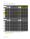
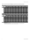
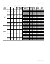
TABLE 14: STATIC RESISTANCES
1000 1200 1400 1600 1800 2000 2200 2400 2600 2800 3000
0.07 0.08 0.09 0.11 0.13 0.15 0.17 0.20 0.23 0.26 0.30
7-15KW 0.04 0.05 0.06 0.07 0.08 0.10 0.12 0.14 0.16 0.19 0.22
20-30KW 0.06 0.07 0.08 0.09 0.11 0.13 0.15 0.17 0.20 0.23 0.26
0.06 0.07 0.08 0.09 0.10 0.11 0.12 0.14 0.16 0.19 0.22
0.08 0.10 0.12 0.14 0.16 0.18 0.20 0.23 0.26 0.29 0.32
COOLING ONLY
2
RESISTANCE, IWG
CFM
DESCRIPTION
ECONOMIZER
1 3
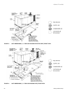
BOTTOM DUCT CONNECTIONS
1
ELECTRIC
HEATERS
1
1. Deduct these resistance values from the available external static pressure shown in SUPPLY AIR BLOWER PERFORMANCE Tables.
3. The pressure through the economizer is greater for 100% outdoor air than for 100% return air. If the resistance of the return air
duct system is less than 0.25 IWG, the unit will deliver less CFM during full economizer operation.
2. Add these resistance values to the available static resistance values on SUPPLY AIR BLOWER PERFORMANCE Tables.
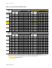
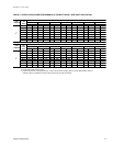
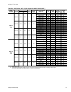
TABLE 15: ELECTRIC HEATER CFM LIMITATIONS
UNITMODEL SIZE NOMINAL
TONS
VOLTAGE
MINIMUM SUPPLY AIR CFM
HEATER SIZE NOMINAL KW
5 7 10 15 20 30
3
208/230-3-60 1100 1100 1200 1200 1300 -
460-3-60 - 1100 1200 1200 1300 -
575-3-60 - - 1200 1200 1300 -
4
208/230-3-60 1300 1300 1300 1300 1300 -
460-3-60 - 1300 1300 1300 1300 -
575-3-60 - - 1300 1300 1400 -
5
208/230-3-60 1600 1600 1600 1600 1600 1600
460-3-60 - 1600 1600 1600 1600 1600
575-3-60 - 1600 1600 1600 1600 1800
6
208/230-3-60 1800 1800 1800 1800 1800 1800
460-3-60 - 1800 1800 1800 1800 1800
575-3-60 - - 1800 1800 1800 1800