


363857-YUM-A-0208
Johnson Controls Unitary Products 3
INPUT
The correct heat capacity of the furnace is regulated by the
main burner orifices and the gas pressure. The proper ori-
fices for natural gas are furnished but the gas pressure regu-
lator must be adjusted by the installer or gas company
service person.
OPERATING INSTRUCTIONS
TO SHUT DOWN THE FURNACE:
1. Close the main gas shutoff valve(s).
2. Turn off the electric power supply.
TO LIGHT THE FURNACE:
1. Do not attempt to light manually.
2. Open the main gas shutoff valve(s).
3. Turn on the electric power supply.
4. Initiate a call for heat.
5. If the return air temperature is below the set point of the
controller, the ventor fans will operate. After an adequate
purge time, the intermittent ignition device will light the
burners. The burners will extinguish and relight automati-
cally upon the demand of the controller.
VENT SAFETY SYSTEM
Each gas furnace module is equipped with an automatic
reset high temperature limit and rollout switch. In the unlikely
event of a sustained main burner flame rollout, the switch will
shut off the flow of gas by closing the main gas valve. The
ignition module will also be disabled, preventing the flow of
gas to the valve. The rollout switch for each module is located
inside the gas heat section access door on the heat shield of
each module. Flame rollout can be caused by blockage of the
power vent system or improper gas pressure adjustment. If
this occurs the furnace will not operate properly, gas supply
to the furnace should be shut off and no attempt should be
made to place the furnace in operation. The system should
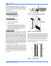
be inspected by a qualified service person. Refer to Figure 3
for a typical installation of vent hoods.
The ignition modules are designed such that if the furnace
fails to ignite after 3 trials for ignition after a call for heat the
flow of gas will be shut off and the ignition module will lock out
for one hour. Then the modules will retry ignition and repeat
cycle until ignition occurs, or call for heat is satisfied or power
to unit is removed. If the furnace does not light after several
tries, a service man should be called to determine the cause
of the problem.
This furnace is equipped with a blocked vented shut-off sys-
tem (air proving switch). The purpose of the switch is to prove
that there is combustion air being drawn through the heat
section. The ignition control will not operate if this switch is
not made in the pre-purge time of the vent assembly. In the
event that the furnace fails to operate due to the pressure
switch, a qualified service agency should be contacted.
Determine that external vent is in place (field installed) and
clear and free of obstructions.
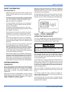
FIGURE 2 - TYPICAL FLAME APPEARANCE
FIGURE 3 - FLUE VENT ASSEMBLY
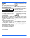
FIGURE 4 - FILTER ACCESS
HEAT EXCHANGER TUBE
BURNER FLAME
(BLUE ONLY)
IGNITOR
BURNER BRACKET
BURNER
GAS
SUPPLY
PIPE
EXHAUST VENT OUTLET
VENT FLUE ASSY.
COMBUSTION AIR INLET
HEAT SECTION DOOR
SHIPPING LABELS
(REMOVE SHIPPING
LABELS PRIOR TO
VENT INSTALLATION)
FILTER CHANNEL
EXTERNAL
UPRIGHT
FILTER CHANNEL
FILTER
BRACKET
PERIMETER FRAME
EXTERNAL
UPRIGHT
FILTERS
BASE RAIL
FILTERS