


Subject to change without notice. Printed in U.S.A. 292443-XTG-B-0807
Copyright © 2007 by Unitary Products Group. All rights reserved. Supersedes: 292443-XTG-A-0207
Unitary 5005 Norman
Products York OK
Group Drive 73069
to shipment. All unit wiring shall be both numbered and
color coded. All units shall be manufactured in a facility cer-
tified to ISO 9001 standards, and the cooling performance
shall be rated in accordance with DOE and ARI test proce-
dures. The heating performance shall be rated to DOE and
GAMA test procedures. Units shall be CSA listed and classi-
fied to ANSI Z21.47/CAN/CSA 2.3 standards and UL 1995/
CAN/CSA No. 236-M90 conditions.
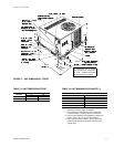
UNIT CABINET
Unit cabinet shall be constructed of G90 galvanized steel,
with exterior surfaces coated with a non-chalking, powdered
paint finish, certified at 1000 hours salt spray test per ASTM-
B117 standards. The unit top shall be a single piece “Water
Shed” design, with drip edges and no-seam corners to pro-
vide optimum water integrity. Unit shall have a rigidly
mounted condenser coil guard to provide protection from
objects and personnel after installation. Indoor blower section
shall be insulated with up to 3/4” thick, aluminum, foil faced
insulation, fastened to prevent insulation from entering the air
stream. Cabinet panels shall be “large” size, easily remov-
able for servicing and maintenance, with built-in lift handles.
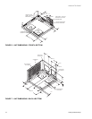
Unit shall be built on a formed, “Super-Structure” design base
pan, with embossments at critical points to add strength,
rigidity and aid in minimizing sound. Full perimeter base rails
shall be provided to assure reliable transit of equipment,
overhead rigging, for truck access and proper sealing on roof
curb applications. Base rails shall be removable, when
required, to lower unit height. Filters shall be furnished and
be accessible through a removable access door, sealed air-
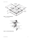
tight. Units vertical discharge and return duct configuration
shall be designed to fit between standard 24” O.C. beams
without modification to building structure, duct work and base
unit. Condensate pan shall be internally sloped and conform
to ASHRAE 62-89 self-draining standards, with 3/4” NPTI
copper, ridged mount connection.
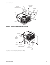
INDOOR (EVAPORATOR) FAN ASSEMBLY
Fan shall be direct drive, multi-speed design. Job site
selected (BHP) brake horsepower shall not exceed the
motors nameplate horsepower rating. Fan wheel shall be
double-inlet type with forward-curved blades, dynamically
balanced to operate smoothly throughout the entire range of
operation. Airflow design shall be constant air volume. Bear-
ings shall be sealed and permanently lubricated for longer life
and no maintenance. Fan assembly shall be “Slip Track”
(slide-out) design for easy removal and cleaning.
OUTDOOR (CONDENSER) FAN ASSEMBLY
The outdoor fan shall be of the direct-driven propeller type,
discharge air vertically, have aluminum blades riveted to cor-
rosion resistant steel spider bracket and shall be statically
balanced for smooth operation. The outdoor fan motor shall
be totally enclosed with permanently lubricated bearings and
internally protected against overload conditions.
REFRIGERANT COMPONENTS
Compressors:
a. Shall be fully hermetic type, direct drive, internally
protected with internal high-pressure relief and over
temperature protection. The hermetic motor shall be
suction gas cooled and have a voltage range of + or
- 10% of the unit nameplate voltage.
b. Shall have internal isolation and sound muffling to
minimize vibration and noise, and be externally iso-
lated on a dedicated, independent mounting.
Coils:
a. Evaporator and condenser coils shall have alumi-
num plate fins mechanically bonded to seamless
internally enhanced copper tubes with all joints
brazed.
b. Evaporator coil shall be of the direct expansion,
blow through design, while condenser coil shall be
draw through design.
Refrigerant Circuit and Refrigerant Safety Components:
a. Shall include independent fixed-orifice expansion
devices.
b. Shall include filter/strainer to eliminate any foreign
matter.
UNIT OPERATING CHARACTERISTICS
Unit shall be capable of starting and running at 125º F out-
door temperature, exceeding maximum load criteria ARI
Standard 210/240. The compressor, with standard controls,
shall be capable of operation down to 45º F outdoor tempera-
ture. Accessory low ambient kit shall be available for opera-
tion to 0º F.
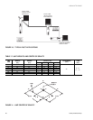
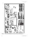
ELECTRICAL REQUIREMENTS
All unit power wiring shall enter unit cabinet at a single factory
provided location and be capable of side or bottom entry, to
minimize roof penetrations and avoid unit field modifications.
Separate side and bottom openings shall be provided for the
control wiring.