


E
G
6
The transformer must also not be mounted
within 0.6m of a bath or shower cubicle, up to a
height of 2.25m.
The transformer must not be mounted where
ambient temperatures are likely to exceed 40°C.
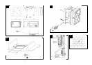
1. Remove the two screws securing the cover,
remove cover.
2. Position the transformer on the wall, and mark
the two fixing holes.
3. Drill and plug the two holes and fix the
transformer with the screws supplied.
For loft mounting:
The transformer can be fixed to a wooden surface
with the two screws supplied.
For fixed surface wiring:
Use the rectangular knockouts on each side (X).
These accept 25 x 16mm trunking (not supplied)
For concealed wiring:
Use the round knockouts (Y).
For connection to a window mounted fan:
Use knockout (Z). Use flexible cable.
When using the side entries with flexible cable, a
hole suitable for the cable size must be made
centrally in the rectangular section.
1. Isolate the electricity supply and remove all
fuses.
The terminal block will accept cable up to
1.5mm².
2. A means for disconnection in all poles must be
incorporated in the fixed wiring in accordance
with the wiring rules.
3. Use suitably rated 3-core or 4-core cable
dependent on application.
4. Remove the retaining screws of the terminal
cover •, if still in position.
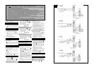
5. Wire the fan as shown in F using the cable
clamp provided. Check fan model to diagram.
LVDX200T: “LH” = Live (High Speed) /
“LL” = Live (Low Speed)
6. Replace the terminal cover • and fasten the
retaining screws.
7. See section on “User adjustments” if you wish
to use settings other than those that have been
factory set.
8. Refit the front cover • (Fig. C).
9. Connect the cable from the isolating switch to
electrical supply wiring, and re-check
installation.
10. Refit fuses before turning on electricity supply.
11. For fixed wiring circuits, the protective fuse
for the appliance must not exceed 5A.
For Australia Only
LVCF20 – Connection to the supply – flexible 3-
core cable with 3 pin plug top for insertion into an
approved 10A wall mounted surface switch with at
least 3mm clearance between contacts.
ALL OTHERS – Permanently connected to the
supply and a remote switch controls operation. They
should be directly wired to the supply through an
approved 10A wall mounted surface switch with at
least 3mm clearance between contacts.
Always wire via the cable clamp.
1. Remove the cable clamps.
2. Wire the transformer as shown in F. Check the
fan model to diagram.
3. Ensure all connections are tight.
4. Replace the clamps and two screws. Ensure the
cable is firmly retained by the clamp.
5. Replace the transformer cover with the two
screws.
6. Switch off the mains electrical supply and
remove fuses.
7. Connect the cable from the isolating switch to
the electrical supply wiring.
8. For fixed wiring circuits the protective fuse for
the appliance must not exceed 5A.
Before making any adjustments, isolate the fan
completely from the mains supply, check
specification below to see which features apply to
your fan.
1. Remove the front cover and replace after
adjustment (Fig. C).
There are no user adjustments for the LVDX200 fan.
1. The timer over-run period can be adjusted
between approximately 30 seconds and 20
minutes. Use an electrician’s screwdriver and
turn screw “T” (Fig. D), clockwise to increase
time, anti-clockwise to decrease. (Factory
preset to approximately 10 minutes).
1. The humidity setting is adjustable between
approximately 50% and 90% relative
humidity. Use an electrician’s screwdriver, and
turn screw “RH” (Fig. D), clockwise to
increase the relative humidity setting and anti-
clockwise to decrease. (Note: the fan is more
sensitive at 50% RH than at 90%).
1. The timer over-run period can be adjusted
between approximately 30 seconds and 20
minutes. Use an electrician’s screwdriver and
turn screw “T” (Fig. D), clockwise to increase
time, anti-clockwise to decrease. (Factory
preset to approximately 10 minutes).
2. The humidity setting is adjustable between
approximately 50% and 90% relative
humidity. Use an electrician’s screwdriver, and
turn screw “RH” (Fig. D), clockwise to
increase the relative humidity setting and anti-
clockwise to decrease. (Note: the fan is more
sensitive at 50% RH than at 90%).
Operate the fan using the external On/Off switch.
Repeat to switch off. The fan speed is pre-set by the
Installer to either high or low speed.
Both speeds can be selected when wired through a
change over switch Part No. 90108AW.
Operate the fan using the external on/off switch.
Repeat to switch off.
When the switch is turned off, the fan continues to
operate for the selected over-run timer period. Top
light “I” is lit when the external on/off switch is
turned on.
The fan speed is pre-set by the installer to either
high or low speed. (If a change over switch has been
installed then the user can switch between high
speed and low speed.)
Time delay start feature on or off
This is set by the installer to provide a 2-minute time
delay start when the fan is switched on using the
external on/off switch.
Switched Operation
The fan can be wired with a separate on/off switch.
Fan operates at condensation speed when switched
on. Top light “I” is lit when the separate on/off
switch is switched on. When switched off, the fan
will continue to operate if the humidity level has not
reached that set by adjusting screw “RH”.
LVCF20T only: When switched off, the fan
continues to operate for the adjustable timer over-
run period.
Condensation Operation
The fan operates at condensation control speed,
when the relative humidity exceeds the set level, and
turns off when the humidity drops.
Boost Operation
The integral pull cord switch switches the fan to run
at high speed. Bottom light “II” is lit when the fan is
operating at high speed. Note: If the separate on/off
switch and integral pull cord are both on, the lights
“I” and “II” will both be lit and the fan will run at
high speed.
Trickle feature on or off
This is set by the installer to provide continuous
background extraction, when the humidity level is
below that set by adjusting screw “RH”.
Time delay stat feature on or off
This is set by the installer to provide a 2-minute time
delay start when the fan is switched on using a
separate on/off switch.
1. Before cleaning, isolate the fan completely
from the mains supply.
2. Only clean the external surface of the fan,
using a damp lint free cloth.
3. Do not use strong detergents, solvents or
chemical cleaners.
4. Allow the fan to dry thoroughly before use.
5. Apart from cleaning, no other maintenance is
required.
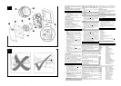
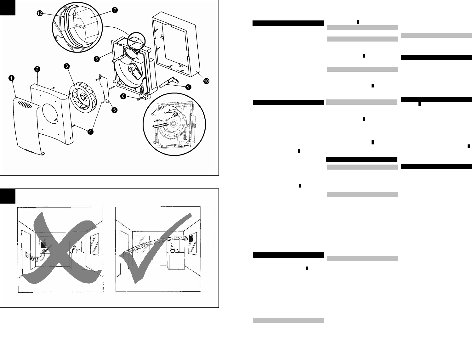
See Diagram E
1. Baffle Plate
2. Front Cover
3. Impeller
4. Fixing Screws
5. Terminal Cover
6. Fan Box
7. Circular Spigot
8. Clamp screws and wall plugs – 3 off
9. Fan body clamps – 3 off
10. Surround
11. Ceiling screws 25mm long - 4 off (Diagram B)
12. Foam Tape
PLEASE LEAVE THIS LEAFLET WITH THE
FAN FOR THE BENEFIT OF THE USER
For speed and ease of installation, your installation
may require some of the Ancillaries listed below:
WD100 Wall Duct
CFWG100 Wall Grille
XCT100 Condensation Trap
DGW/B Air Replacement Grille
SP100 Spigot Plate
XAA Air Brick Adaptor
VC10 Vent Cowl
WT10 Termination Ducting Kit
XF/FM Flat Ducting (Plastic/Metal)
(Plastic 234x29
Metal 230x25)
VK10 Wall Vent Kit
FD100 Flexible Ducting
WDC5 Worm Drive Clips
XCMK Ceiling Mounting Kit
XBP In-Line Back Draught Shutter
EFT Easy Fit Termination Kit
GMK Glass Mounting Adaptor
PDXGF Grease Filter
FDA Flat Duct Adaptor Kit
Spares
Listed below are some of the spares available. See
back page of this booklet for ordering details:
41756SK Motor (LVDX200T)
41757SK Motor (LVCF20/LVCF20T)
41758SK PCB Assy. (LVDX200T)
41759SK PCB Assy. (LVCF20)
41760SK PCB Assy. (LVCF20T)
41769SK Front Cover c/w Baffle
(LVDX200T)
41770SK Front Cover c/w Baffle
(LVCF20 / LVCF20T)
41740SK Surround Moulding
(Entire Range)
41741SK Pull-Cord Assembly
(Entire Range)
41742SK Impeller (Entire Range)
Fixing the transformer directly
Wire the Fan
Wire the Transformer
User adjustments
LVDX200
LVDX200T
LVCF20
LVCF20T
Using the Fan
LVDX200
LVDX200T
LVCF20 / LVCF20T
LVCF20T only
Cleaning
Key
Ancillary Options
3