


GB
Xpelair
Toilet/Bathroom
Fans LV100,
LV100PC, LV100T,
LV100H, LV100HP &
LV100PIR
installation &
operating
instructions
Please leave this leaflet
with the fan for the
benefit of the user
6
If installing in a ventilation shaft
1. Check there are no buried pipes or cables
in the ventilation shaft.
If in doubt, seek professional advice.
2. Cut a hole 110mm in diameter, in the side of
the shaft.
3. If the shaft has cavity walls, use the wall tube
to bridge the cavity.
4. Fit ducting and condensation trap if
necessary, positioning condensation trap as
near to the fan as possible.
If installing in a ceiling
1 Check there are no buried pipes or cables
in the ceiling joists etc.
If in doubt, seek professional advice.
2 Cut a hole 115mm diameter.
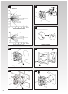
Preparing the fan for installation
Remove the front cover by pressing the release
catches located on the sides of the unit with a
3mm screwdriver, whilst pulling the front cover
forward M
Mount the fan in the hole
If working above Ground Floor Level,
appropriate safety precautions must be
observed.
If installing in a wall, ceiling or vent
Mark the position of the back plate B
1. Hold the back plate so that the terminal block
faces you in the left hand corner, and the lip
points towards the hole.
2. Carefully insert the lip into the wall
duct/ceiling or vent shaft.
3. Adjust the position of the back plate until it is
level.
4. Mark on the wall/ceiling or vent shaft the
positions of the three fixing holes in the back
plate.
5. Remove the back plate from the ducting.
6. Drill screw holes in these positions if
necessary, and fit wall plugs if necessary.
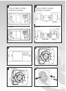
Mount the back plate C
1. Push the ribbed gasket (RG100) onto the lip
of the back plate 1
2. If installing in a ceiling or vent, push the
larger diameter piece of the telescopic wall
tube onto the ribbed gasket. Cut the tube to
the required length, if necessary.
3. If wiring the fan from behind, remove
knockout. Feed the mains cable through the
cable entry hole in the backplate to the
terminals D
4. If wiring from above, leave the cable free to
be fitted into labyrinth.
5. Insert the lip of the back plate into the wall
duct/ceiling or vent shaft as before.
6. Fasten the back plate to the wall/ceiling or
vent shaft using appropriate fasteners. If
using screws, do not overtighten the
screws.
Mount the back draught shutter
1. Peel the backing from the foam strip supplied
and attach it around the outside of the lip on
the back draught shutter.
2. Go outside. Holding open the top and bottom
vanes, insert the lip into the wall duct.
3. Making sure the back draught shutter is level,
mark the positions of the two fixing holes in
the top right hand and bottom left hand
corners.
4. Remove the back draught shutters from the
wall duct.
5. Drill screw holes in these positions, and fit the
remaining wall plugs.
6. Holding open the top and bottom vanes, refit
the back draught shutter and fasten it to the
wall using the pointed end self-tapping
screws. Do not overtighten screws.
7. Make sure the vanes open and shut freely.
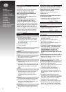
If installing in a window or panel
Sealing the hole E
If installing in a window or panel no more than
9mm thick, fit the white rubber gasket around the
edge of the hole. If installing in a panel or sealed
double glazing more than 9mm thick, a DXG
Double Glazing kit is required. Follow the
instructions supplied with the special kit.
Attach the back draught shutter to the spacer F
1. Holding open the top and bottom vanes,
insert the back draught shutter 2 into the
spacer 3 so that the fixing holes in the top
right and bottom left hand corners match
those on the spacer.
2. Insert two of the flat ended self-tapping
screws provided and fasten the back draught
shutter to the spacer.
Mount the fan in the window G
1. Someone else must hold the back draught
shutter and spacer in position outside, with
the spacer against the glass.
2. Make sure that the two raised fixing holes in
the spacer are horizontal and are positioned
within the hole.
3. From inside, hold back plate so that the
terminal block faces you in the top left hand
and the lip points towards the hole.
4. Align the holes in the back plate with those in
the spacer.
5. Insert two of the flat ended self-tapping
screws provided in the fixing holes, and
fasten the back plate to the spacer. Do not
overtighten the screws.
Mounting the transformer I
The transformer can be fixed directly to the wall
or attached to a suitable recessed wall box.
If fixing directly
1. Remove two screws securing the cover,
remove cover.
2. Position the transformer on the wall and mark
the two fixing holes “A” and “C”.