


7
Controllers
#6-32 x 5/16 PH Flat Hd
Screw (4)
#6-32 x 1/2 Slot White
Oval Hd Screw (4)
Decorator Style
Cover Plate
Water tight
WATERPAD™
Unit
(side view)
Adapter Plate
CAUTION:
Pressure Relief Hole. See step 7 below.
#4-40 x 1/4 PH Pan Hd Screw (1)
and O-ring (1). Install into Relief Hole
at installation site only. See text.
#6-32 x 3/4 PH Flat Hd
Screw (4)
1
"J"-Box
(Retro-Fit type)
3
4
5
2
6
7
8
9
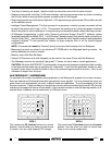
1/8" diameter x 1/4" deep
clearance holes (4) for
Cover Plate mounting
screws (see step 2 below).
Wall Material
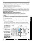
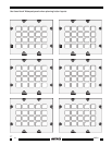
Fig. 6 Mounting the Waterpad into a Retrofit type J-box.
• For retrofit (existing construction) appli-
cations, use high volume boxes, such
as the 2-gang Slater Retrofit 32 cu. inch
box.
• Most high volume new construction J-
boxes will work. A "P" ring could also be
used.
• NOTE: Be sure to check fit
before
buying large quantities of J-boxes for
the job.
• Since the Waterpad is fully enclosed, it
may be possible, with some types of
sturdy wall materials, to mount it di-
rectly to the wall surface. See Fig. 9.
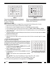
Mounting Procedure - Retrofit J-Box
To mount the Waterpad using a retrofit J-box, refer to Fig. 6 and proceed as follows:
1. Temporarily mount or hold the J-box to the wall opening.
2. Using the Adapter Plate
(supplied) as a template,
mark, then drill four 1/8" x 1/4"
holes in the wall material to
allow clearance for the ends
of the #6-32 x 1/2" cover plate
screws . This allows the
cover plate to be pulled down
flush to the wall in step 9. See
Figs. 6 & 8.
3. Thread the 6-foot cable from
the Waterpad through the
Adapter Plate and through
a knockout hole in the back of
the J-box .
4. Run the 6-foot cable from the
back of the J-box to a dry
location in an adjacent com-
partment or room and make connections to the 8-terminal block and the 4-conductor inter-room cable.
Refer to Figs. 3 & 7.
5. Attach the J-box to the wall.
6. Attach the Adapter Plate to the J-box using the four #6-32 x 3/4" Flat Hd screws (supplied).
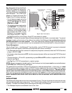
7. Install the #4-40 x 1/4" Pan Hd screw and O-ring (supplied) into the Pressure Relief Hole . Tighten
until you see some compression of the O-ring.
CAUTION: A Pressure Relief Hole is provided to prevent the buildup of internal pressure that could
damage the membrane during"storage and shipping conditions. When the Waterpad is installed at
the final site, however,
the screw and O-ring must be installed prior to exposure to moisture!
Failure to do so will void the warranty!
8. Using the four #6-32 x 5/16" PH Flat Hd screws (supplied), attach the Waterpad to the Adapter
Plate . See Figs. 6 & 7.
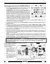
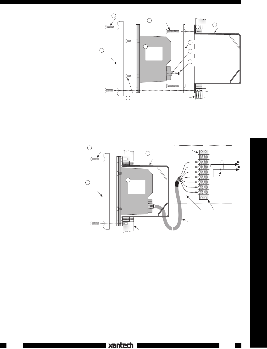
Fig. 7 Installed Waterpad - Using a Retrofit type J-box.
+12V
(red)
RX
(blue)
TX
(brown)
GND
(black)
IR OUT
(white)
COMMON
(orange)
STATUS
(green)
Decorator Style
Cover Plate
6-foot, 7-Conductor Cable
"J"-Box
(Retro-Fit type)
Wall Material
4
9
1
#6-32 x 1/2 Slot White
Oval Hd Screw (4)
Water tight
WATERPAD™
Unit
(side view)
2
8-Terminal Block
4-Conductor
Inter-room cable
(to controlled
equipment).
Cable End and Terminal Block
(located in a dry area or compartment)
WPK1