


8
Wall Material
#6-32 x 3/4 PH Flat Hd
Screw (4)
3
Water tight
WATERPAD™
Unit
(side view)
2
#6-32 x 1/2 Slot White
Oval Hd Screw (4)
1
#6-32 x 5/16 PH Flat Hd
Screw (4)
8
Decorator Style
Cover Plate
9
Adapter Plate
CAUTION:
Pressure Relief Hole. See step 7, page 8.
#4-40 x 1/4 PH Pan Hd Screw (1)
and O-ring (1). Install into Relief Hole
at installation site only. See text.
5
6
7
"J"-Box
(New Construction
Type)
4
1/8" x 1/4" clearance holes (4)
for Cover Plate mounting
screws (see text).
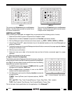
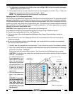
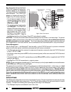
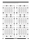
Fig. 8 Mounting the Waterpad into a New Construction type J-box.
9. The final step is to attach the Decorator Cover Plate (supplied) to the front of the Waterpad assembly
using the four #6-32 x 1/2" Slot White
Oval Hd screws (supplied).
Mounting into a New Construction
J-Box
The procedure to mount the Waterpad
into a new construction type J-box is
essentially the same as that for a retrofit
J-box.
1. The main difference is that you will
need to have access to the rear of
the new construction J-box so that
the 6-foot, 7-conductor cable can be
pulled through the knockout hole
and run to a dry location in an adja-
cent compartment or room.
2. You would then make connections
to the 8-terminal block and the 4-
conductor inter-room cable and carry out all the remaining steps as described for retrofit J-box
mounting. Refer to steps 1 through 9 previous and Fig. 8.
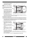
Mounting Directly to a Wall Surface
If the wall material is sufficiently strong so that it will hold the threads of sheet metal or wood screws, you
may be able to mount the Waterpad directly to the wall surface. Refer to Fig. 9 and proceed as follows:
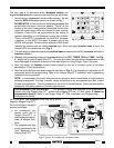
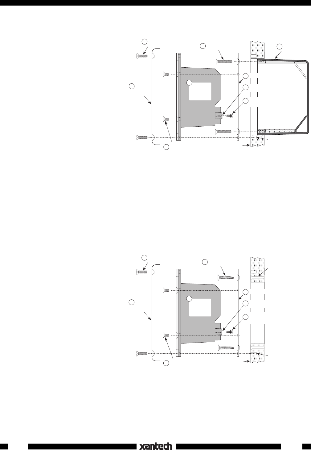
1. Use the Adapter Plate as a template to mark a cutout opening for the Waterpad on the wall and to
locate pilot holes for the four Adapter Plate mounting screws . Also, mark spots for clearance holes
for the ends of the #6-32 x 1/2" cover plate screws .
2. Cut the opening for the Waterpad.
3. Using a #32 bit, drill four counter-
sunk pilot holes 3/4" deep for the
Adapter Plate and the mounting
screws .
4. Drill four 1/8" x 1/4" holes in the wall
material to allow clearance for the
ends of the #6-32 x 1/2" Cover Plate
screws .
5. Using the four #6 x 3/4" Flat Hd
Sheet Metal screws (supplied),
attach the Adapter Plate to the
wall.
6. Run the 6-foot 7-conductor cable
from the Waterpad through the wall
opening to a dry location in an adja-
cent compartment or room. Make connections to the 8-terminal block and the 4-conductor inter-room
cable. Refer to Figs. 3 & 7.
7. Finish by following steps 7 through 9 under "Mounting Procedure - Retrofit J-Box".
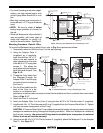
Fig. 9 Mounting the Waterpad directly onto a wall without a J-box.
Wall Material
#6 x 3/4" PH Flat Hd
Sm Screw (4)
3
Water tight
WATERPAD™
Unit
(side view)
2
#6-32 x 1/2 Slot White
Oval Hd Screw (4)
1
#6-32 x 5/16 PH Flat Hd
Screw (4)
8
Decorator Style
Cover Plate
9
Adapter Plate
CAUTION:
Pressure Relief Hole. See step 7, page 8.
#4-40 x 1/4 PH Pan Hd Screw (1)
and O-ring (1). Install into Relief Hole
at installation site only. See text.
5
6
7
1/8" x 1/4" clearance holes (4)
for Cover Plate mounting
screws (see text).
0.116" (#32 drill bit) x 3/4"
countersunk pilot holes (4)
for Adapter Plate & mounting
screws. (See step 3 above).
WPK1