


’
3.
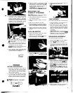
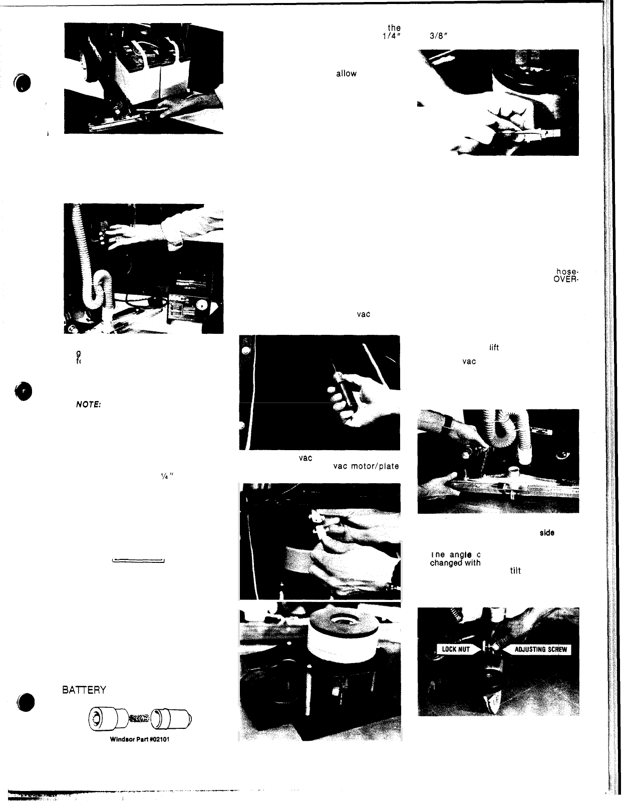
Connect the “DC” charger plug to the
connector on the machine.
NOTE
A
safety override switch is activated
when the “DC charge plug is connected.
This prevents all panel circuits on the
machine from accidentally being
switched on during charging cycle.
4.
Connect charger “AC” plug to properly
rounded outlet that has correct voltage
B
or the charger.
5.
The charger suppled by Wlndsor is
totally automatic and shuts off when
the batteries are fully charged.
NOTE
Refer to the charger manual for
detailed charging information.
6.
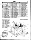
After charging check electrolyte level
of the batteries. Add distilled water to
the level as shown in diagram.
’/4
”
FROM
BOTTOM
OF TUBE
BATTERY MAINTENANCE
1.
Keep tops of batteries clean and dry.
Use a damp cloth with a weak solution
of baking soda or ammonia and water.
Use a clean dry cloth to wipe battery
tops dry after cleaning.
2.
If corrosion (white deposits) appears
on the battery terminals and cable
clamps, remove and clean. Use a battery
terminal and connector cleaning tool.
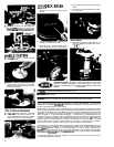
BAlTERY TERMINAL CLEANER
Wlndsor
Pall
M2101
3.
Keep the battery electrolyte at th$
correct level
-
approximately
114
below bottom of filler tube of each cell.
Distilled water should be added, as
needed,
AFTER
charging cycle.
WARNING:
Do not allow electrolyte
level to drop below the tops of the plates.
SERVICING THE
COMPACT SCRUBBER
CAUTION:
Before making any adjust
-
ments or repairs to the machine.
.
.
1.
Only qualified maintenance personnel
are
to
perform repairs.
2.
Make sure battery charger is discon
-
nected.
3.
Make sure all switches are “OFF”.
4.
Remove batteries as required or discon
-
nect main battery leads from batteries
when making repairs to electrical system.
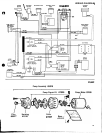
5.
Refer to wiring diagram when replacing
electrical parts or repairing electrical
system.
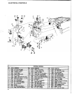
VACUUM
MOTOR
1.
Disconnect battery leads and remove
batteries from compartment.
2.
Remove
(6)
screws holding vac motor/
plate assembly to recovery tank.
3.
Disconnect vac motor lead from con
-
nector and lift out vac motor/plate
assembly.
4.
Check motor brushes. When worn to
318”
replace both brushes.
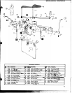
PUMP
ASSEMBLY
(On models equipped with auxiliary pump)
1.
Remove batteries and squeegee as
-
sembly. Lay machine on side.
2.
Disconnect pump motor leads. Re
-
move
(4)
screws holding pump to
chassis. Disconnect solution hoses
from pump head and lift out pump.
Refer to pump drawing for replace
-
ment parts.
CAUTION:
When replacing hose-
barbs on pump head
-
DO NOT OVER-
TIGHTEN
-
as this could crack intake
and exhaust ports in pump head.
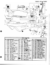
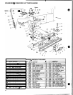
SQUEEGEE ASSEMBLY
To remove squeegee assembly.
.
1.
Raise squeegee lift arm to store position.
2.
Remove vac hose from squeegee.
3.
Pull retaining pin from locator stud.
Push down and slide squeegee to the
right to disengage right hand stud from
drag arm.
4.
When installing or replacing squeegee
blades make sure the
smooth
side
of the
blade is next to the squeegee casting.
5.
The an
18
of the squeegee can be
changejwith the adjusting screw. Turn
screw clockwise to
tiit squeegee for
-
ward and counterclockwise to tilt rear
-
ward. Tighten lock nut after making
adjustment.
6.
Down pressure can be increased or
decreased with the adjusting nut.
5