


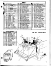
TROUBLE
-
SHOOTING
GUIDE
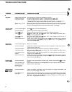
PROBLEM PROBABLE CAUSE CORRECTIVE ACTION
I
No
power.
Battery cables corroded
at battery terminals.
Faulty main switch.
Faulty safety override
switch.
1. Clean battery cable clamps and battery terminals.
2.
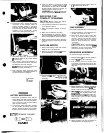
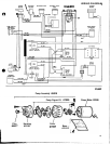
Check voltage at points
A
and B. Voltage should be
22/26
VDC.
1. Check voltage at points
B
and C. Voltage should be
22/26
VDC.
2.
Turn main switch on and check voltage at points B and D. Voltage should be
With main switch
“ON” check voltage at points B and
G,
and B and
H.
If
no voltage
at B and
H
remove leads and check micro
-
switch for continuity. Should have con
-
tinuity in normal position and no continuity when switch is activated.
22/26
VDC.
If
no voltage remove leads and check switch for continuity.
Vacuum motor
does not run.
Brush motor
does not run.
Solution
light
does not work.
Battery charge
level lndlcator
does not light.
14
Circuit breaker tripped.
Loose connection.
Faulty
vac switch.
Faulty
vac relay.
Faulty
vac circuit
breaker.
Motor brushes worn.
Circuit breaker tripped.
Loose connections.
Faulty brush switch.
Faulty brush relay.
Faulty brush circuit
breaker.
Motor brushes worn.
Loose connections.
Faulty solution light.
Light stays on with
solution lever in
“OFF” position.
Loose connections.
Faulty PC Board or
faulty light.
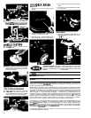
Reset
vac motor circuit breaker
(20
amp).
Check motor lead connections at terminals.
Remove leads and check switch for continuity. Replace as needed.
With main switch
“ON”
and vac switch “ON” check voltage at points B and
I.
Voltage should be
22/26
VDC.
With main switch
“ON”
and vac switch
“ON”
check voltage at points B and
J.
Voltage should be
22/26
VDC.
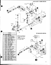
Check motor brushes.
ReDlace when worn
to
318”.
With batteries fullv charaed
and motor secured
,
apply ’battery voltage directly
to
motor.
No
load amp draw of
motor should be
6.2
amps.
Reset circuit breaker.
Check motor leads at terminal block connections (located on inside front of frame).
Tighten screws as needed.
Remove leads and check switch for continuity. Replace as needed.
With main switch
“ON”
and brush switch
“ON”
check voltage at points B and
K.
Voltage should be
22/26
VDC.
With main switch
“ON”
and brush switch
“ON”
check voltage at points B and L.
Voltage should be
22/26
VDC.
Check motor brushes. Replace when worn
to
3/8”. With batteries fully charged
and motor secured, apply battery voltage directly
to
motor.
No
load amp draw of
motor should be
6
to
8 amps.
Check for loose connections at solution light, solution switch and at
vac fan relay
ground.
Remove light and apply direct voltage
(24
VDC)
to
light. Replace light as needed.
Adjust solution light switch.
Check connections at battery card, micro
-
switch at charger Connection, and
ground connection at
vac motor relay.
Check voltage into PC Board (point
T).
Voltage should be
22/26
VDC. Check voltage
across first pin (from right) and eighth pin (from right) point
U.
Voltage should be
8/10
VDC. If voltage is 8/10 VDC replace battery charge level indicator light. If
there is no voltage replace PC Board.