


Installation
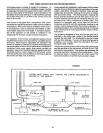
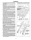
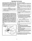
1. Lay an outline of the furnace in the selected location,
and draw diagonally from each corner of the outline as
shown in Figure 6.
2. Drive a nailthrough the flooringat the intersectionof the
diagonal lines.
3. Use the nail location as a reference, and examine the
area beneath the floorto assure there are noobstructions
that will prevent the installation of the furnace and that
adequate clearance between thefurnace and the ground
can be obtained. If the selected locationof the furnace is
appropriate, proceed to step 4.
4. Bore two 1" diameter holes in opposite corners of the
furnace outline. Be sure the holes do not extend beyond
the furnace outline.
5. Insert a compass or sabre saw into one of the 1"diameter
holes and cut along the furnace outline. Cut as straight
and accurately as possible to avoid any possibilitythe
holewill notfit the furnace or willextend beyond the outer
perimeter of the furnace grille after it is installed.
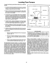
6. Ifitisnecessarytocutflcorjoists to installthefurnace, install
headers across the cut ends ofthe floor joists,and double
the floorjoists along each side of the furnace cut-out as
shown in Figure 7. If you must cut a girder or beam,
constructan adequatefoundationand pillartosupporteach
end of the cut member.
7. If necessary, dig a pit and install a pan in the ground
beneath the furnace to provide the required clearances.
8. Remove the grille from the furnace.
9. Lower the furnace intothe floor opening untilthe flanges
on the furnace cabinet rest on the floor.
11. Fasten the furnace in place by driving nails through the
sides of the furnace cabinet and intothe floorjoists.
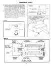
12. Refer to Figure 10 on page 11 for the installation of
drafthood collars and the drsfthood.
13. Install the (2) drafthood collars and gaskets by
positioning the collars intothe (2) retangular openings
on the furnace, making sure gaskets are facina toward
14. Slipthe (2) drafthoodcollars overthe combustion chamber
outlets and engage the collars into the furnace untilthe
gaskets presstightagainstthe furnace. Secure thecollars
to the furnace with (12) screws previously removed.
15. Check to be sure the drafthood collarsfitsnugly over the
combustion chamber outlets.
16. Install the drafthood by positioning the drafthood with
open side down. Slip over the drafthood collars making
sure the drafthood collars engage into the drafthood.
Secure the drafthood to the furnace with (4) screws
previously removed.
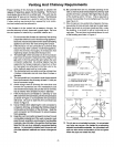
17. Install the pipe necessary to connect the furnace to the
gas vent or chimney. Be sure to comply with all the
requirements for proper venting as stated inthe "Venting
and Chimney Requirements" section of this manual.
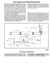
18. Connect the furnace to the gas supply line as specified
by the "Gas Supply and Piping Requirements" sectionof
this manual (see Figure 5).
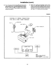
19. Install the thermostat and connect the thermostat lead
wires tothe limitswitchand control as shown in Figure8.
FIGURE 6
1" DIA. HOLE FOR STARTING
LOCATION. DRIVE NAIL
THROUGH FLOORTO
LOCATECENTER
UNDERNEATH,
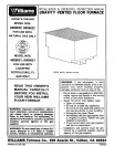
MODEL NUMBER WIDTH LENGTH DEPTH
4505621; 4505622 = 24-1/4 32-3/8 28
6005621; 6005622 = 24-1/4 42-5/8 28
FIGURE 7
NOTE :
IF TWO JOISTS ARE /
CUT,
HEADIER.
T_S SPACE MUST BE
THE SAME SIZE AS
THE OPENING CUT
-9-