Installation (cont.)
INSTALL VENT CAP
Outside, place a single strip of mastic (provided) around
the back flange of the vent cap ("G" Fig. 5, page 8). In-
stall the vent cap by inserting it into the air inlet tube and
over the vent tube.
IMPORTANT
The top of the vent cap is embossed "TOP". Install it in
the correct position to prevent water from entering the wall.
Level the vent cap and attach it to the outside wall with
four (4) #8 roundhead (long) screws (Fig. 6).
If the wall surface is not flat (shiplapped siding, etc.) or
less than 5 inches thickness use Thin Wall Collar Kit (9307)
or, build up a flat surface with wood strips. Do not tilt or
bend cap to fit uneven surfaces. The vent cap flange must
be tight against the wall to prevent rain or wind penetra-
tion. Use standard caulking compound if required (not
provided).
\
For brick, masonry or plaster walls, it may be necessary \
to use lag screws or expanding anchor bolts which are
k
not furnished with the furnace.
POSITION OF VENT CAP
EXTERIOR WALL
Optional Blower Installation and Operating Instructions
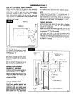
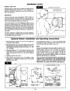
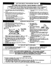
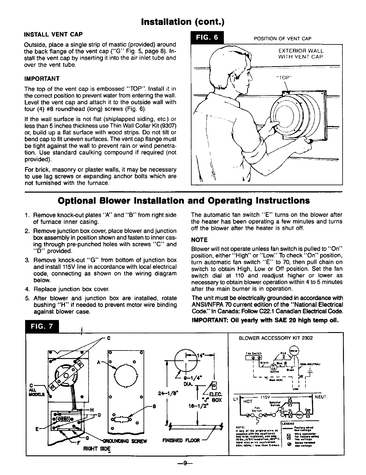
1. Remove knock-out plates "A" and "B" from right side
of furnace inner casing.
2. Remove junction box cover, place blower and junction
box assembly in position shown and fasten to inner cas-
ing through pre-punched holes with screws "C" and
"D" provided.
3. Remove knock-out "G" from bottom of junction box
and install 115V line in accordance with local electrical
code, connecting as shown on the wiring diagram
below.
4. Replace junction box cover.
5. After blower and junction box are installed, rotate
bushing "H" if needed to prevent motor wire binding
against blower case.
The automatic fan switch "E" turns on the blower after
the heater has been operating a few minutes and turns
off the blower after the heater is shut off.
NOTE
Blower will notoperate unless fan switch is pulled to "On"
position, either "High" or "Low." To check "On" position,
turn automatic fan switch "E" to 70, then pull chain on
switch to obtain High, Low or Off position. Set the fan
switch dial at 110 and readjust higher or lower as
necessary to obtain blower operation within 4 to 5 minutes
after the main burner is in operation.
The unit must be electrically grounded in accordance with
ANSI/NFPA 70 current edition of the "National Electrical
Code." In Canada: FollowC22.1 Canadian ElectricalCode.
IMPORTANT: 011yearly with SAE 20 high tamp o11.
0
SCREW
RIGHT
I z- _;/4- i
=,-t/r I
i "J'BOX
-'--8 i 16-1/2"
F1NIItlfl)
BLOWER ACCESSORY KIT 2302
r_lR Swt,¢h Illl4
i • lille• .
I I I
L1 115V _.= • NEUT
=w,t¢_
NOT(: i Fact_ w_N
,,........... ,......... I_ :::'.'J,_:'
.... ,. ............ = I B _-"_:._,,_-,.,
t, _. 4/,4 i,le.=4i f le4t. to_ ¢. U i_ .*lltqt
•ekl er Nle oqllvll _t4. _r 1ill
,,,..-........,-,.I ;


