


Installation
Installation should be done by a QUALIFIED SERVICE TECHNICIAN.
The furnace must be located on an outside wall.
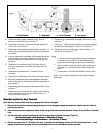
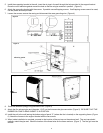
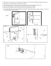
Wall Installation
4
Minimum clearances from combustible materials:
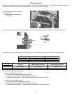
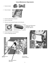
WARNING: For the installation of this furnace, the
following items must be used in the vent air intake
system:
• Unit to the top surface of carpeting, tile:
2-inches (50 mm)
• Unit to back wall (0” to spacers):
0-inch (0 mm).
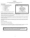
External Vent Cap
• Vent to wall enclosure:
(Part Number: WFR–TRM000)
0-inch (0 mm)
Flanged Air Inlet Tube
• Unit to sidewalls:
(Part Number: WFR–TBO002)
3.15-inches (80 mm)
Flue Outlet Tube
• Unit to ceiling:
(Part Number: WFR–795)
10-inches (254 mm)
O-Ring
(Part Number: WFN–RNG003)
See Figure 1 showing clearance for installation of vent cap.
(All the above items are supplied with the furnace)
Leave at least three-feet in front of the wall furnace for
servicing and proper operation. The wall furnace must be
installed in such a way that the external casing can be completely removed for servicing.
If there is a shelf above the furnace, it must be non-combustible. A minimum clearance of 12-inches (300 mm) is recommended
between the furnace and the non-combustible shelf above it.
Gas equipment installed in residential garages must be installed so that all burners and burner ignition devices are located not
less than 18-inches (460 mm) above the floor. Such equipment must be located, or protected, so it is not subject to physical
damage by a moving vehicle.
The vent terminal of this direct-vent furnace must be located at least 9-inches (230 mm) from any opening through which flue
gases could enter a building. The bottom of the vent terminal and the air intake must be located at least 12-inches (300mm)
above grade.
DO NOT cover the furnace.
Make sure that the correct gas supply is available.
The furnace requires a 120 V 60 Hz electrical supply.
The appliance, when installed, must be electrically grounded in accordance with local codes, or in the absence of local codes
with the National Electrical Code ANSI/NFPA 70 (latest edition) or in Canada with CAN/CSA-C22.2 No. 3.
WARNING: The nearest point of the vent cap should be a minimum horizontal distance of six (6)
feet (1,830 mm) from any pressure regulator. In case of regulator malfunction, the six (6) feet
(1,830 mm) distance will reduce the chance of gas entering the vent cap.